Cashco 3171 User Manual
Model 3171, Back pressure / relief regulator, Caution
CAUTION
Installation of adequate overpressure pro tec tion is
recommended to pro tect the reg u la tor from overpres-
sure and all down stream equip ment from damage in
the event of regulator failure.
The maximum inlet pressure is equal to 1.2 times
the larger number of the stated range spring on
the nameplate, and is the rec om mend ed “up per
op er a tive lim it” for the sens ing diaphragm. High er
press ures could dam age the di a phragm. (Field hy-
dro static tests fre quent ly de stroy dia phragms. DO
NOT HYDRO STATIC TEST THRU AN IN STALLED
UNIT; ISO LATE FROM TEST.)
INSTALLATION, OPERATION & MAINTENANCE MANUAL (IOM)
IOM-3171
12-13
MODEL 3171
BACK PRESSURE / RELIEF REGULATOR
SECTION I
I. DESCRIPTION AND SCOPE
Model 3171 is a back pressure/relief regulator used to control upstream (inlet or P
1
) pressure. Inlet and Outlet size
is 1/2" with Tri-Clamp
®
connections. The 3171 incorporates a stainless steel body. Refer to Tech ni cal Bulletin 3171-
TB for specifi c design conditions and selection recommendations.
CAUTION
This is not a safety device and must not be sub sti tut ed for a code approved pressure
safety relief valve or rupture disc.
SECTION II
II. INSTALLATION
1. An inlet block valve should be installed upstream of
the regulator.
2. If service application is continuous such that shut down
is not readily accomplished, it is rec ommended that
an inlet block valve, outlet block valve, and a manual
bypass valve be installed.
3. An inlet pressure gauge should be located ap prox-
i mately ten pipe diameters upstream, and with in
sight.
4. All installations should include an upstream re lief
device if the inlet pressure could exceed the pres sure
rating of any equip ment or the maximum inlet pressure
rating of the unit.
5. Flow Direction: Install so the fl ow direction match es
the arrow cast on the body. Connect the inlet pressure
to the body side connection. Fluid will relieve out of
the bottom connection.
6. Install unit with spring chamber (2) in the vertical posi-
tion to allow for proper draining.
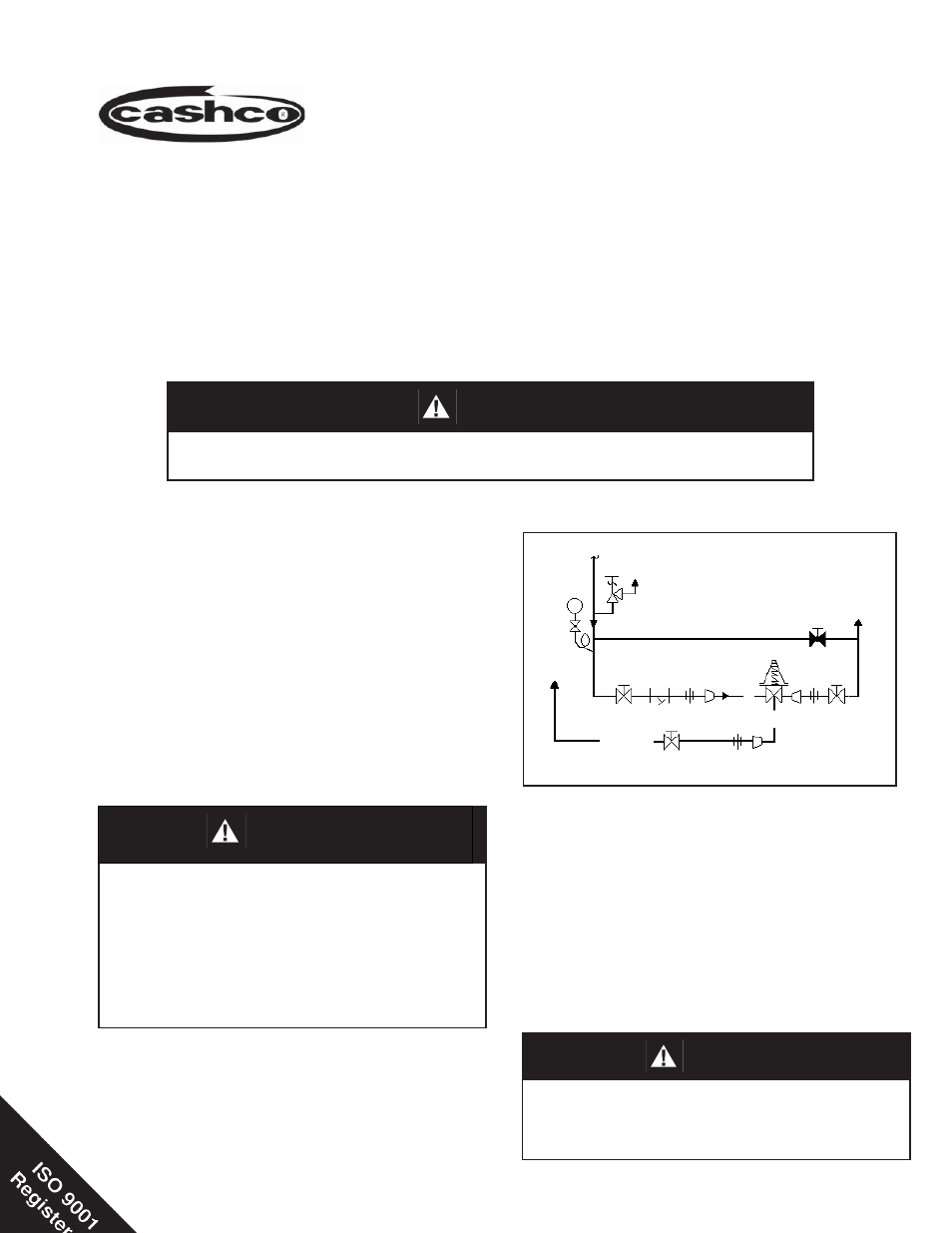
WARNING
_
Supply
@ P1
SRV
PI
System
Bypass
P
2
Discharge
P
1
Model 3171
BP Relief
Regulator
Recommended Piping Schematic for Back Pressure/Relief Station