Vii. maintenance, Warning – Cashco SA1 User Manual
Page 3
IOM-CA1/SA1
3
VII. MAINTENANCE
A. General:
1. The regulator may be serviced without re mov-
ing the regulator from pipeline. The reg u la tor
is designed with quick-change trim to simplify
maintenance.
2. Record the nameplate information to req ui si-
tion spare parts for the regulator. The in for-
ma tion should include: Size, Product Code,
and Serial Number.
3. Refer to Section IX for recommended spare
parts. Only use original equipment parts sup-
plied by Cashco/KM for re build ing or re pair ing
regulators.
4. Owner should refer to owner's procedures for
removal, handling, cleaning and disposal of
nonreuseable parts, i.e. seals, etc.
5. The Inner Trim is re moved and replaced in the
body (23) as an assemblage of parts. The
Inner Trim Assembly, here in af ter called ITA,
consists of the fol low ing parts:
SECTION VII
Item Dynamic
No.
Seal Type
Part Description
13
..................... All
..........................Piston-Guide
Bearing
15 ..................... All ................................ Cage O-ring Seal
16.....................
UC.................................................Shim
19
..................... All
................................................... Cage
20
..................... All
...........................................Valve
Plug
21
..................... All
............................................ Seat
Ring
27 ..................... All ............................. Dynamic Side Seal
27.1 .............. CP............................................. Cap Seal
27.2 .............. CP..........................O-ring Energizer/Seal
27.3 .............. UC .......... U-Cup Seal w/Metal Energizer
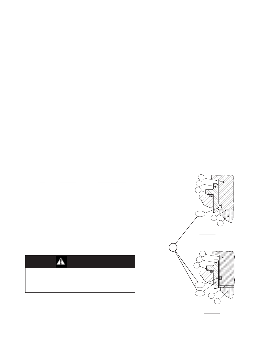
6. A detailed view of the dynamic side seal parts
is shown in Figure 1; an assembled ITA in
Figure 2; and a cross-sectional drawing of
the entire regulator is shown in Figure 3.
Figure 1: Dynamic Side Seals
ing screw (1) CCW (viewed from above) until
removed from spring cham ber (4).
3. Loosen
the
diaphragm
fl ange bolts (12) and
nuts (11) uniformly. Remove all bolting.
4. Place matchmarks on body (23) and spring
chamber (4) fl anges. Remove the spring
cham ber (4) by lifting vertically.
5. Remove the ball (14), spring follower (5) and
range spring (6).
6. Remove upper diaphragm pressure plate (8).
7. Remove diaphragm(s) (9) and examine to
de ter mine if failed. If diaphragms failed, de-
ter mine if op er at ing con di tions are ex ceed ing
designed pressure or tem per a ture limits.
8. Evenly loosen the three cage cap screws (18)
in single revolution increments. The reg u la tor
con tains a lower return spring (22); the ITA
should rise as the cage cap screws (18) are
backed out evenly. A downward holding force
should be ap plied to the top of the piston-guide
bearing (13) to pre vent the ITA from pop ping
up as the last threads of the cage cap screws
(18) are disengaged. Remove washers (17).
Type UC - U-Cup
Dynamic Seal
Type CP - Cap
Dynamic Seal
27
13
13
19
19
20
20
27.3
27.1
27.2
15
15
*
*
*
*
*
*
16
16
WARNING
SYSTEM UNDER PRESSURE. Prior to per form ing
any maintenance, isolate the reg u la tor from the
sys tem and relieve all pressure. Failure to do so
could result in personal injury.
B. Main Regulator Disassembly:
1. Shut down the system in accordance with
Section VI.
2. Loosen adjusting screw lock nut (2) and relax
range spring (6) pressure by turning ad just-