Cashco 1000 Cryogenic User Manual
Page 7
IOM-1000HP-Cryogenic
7
CYLINDER SUB-ASSEMBLY (21) WITH
PISTON (24) – METAL SEATED
CONSTRUCTION
4. If an Option 1000 -17 piston spring (30) is uti-
lized, it also should be removed and re placed
at trim replacement.
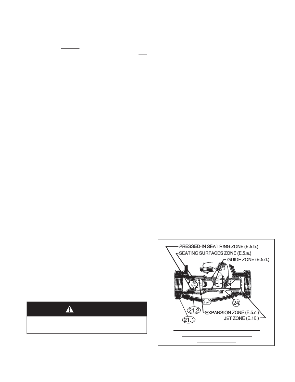
5. Inspect inside surface of cylinder (21) at four
points:
a. Valve seat (21.2) ring erosion/wear on
seat ing surfaces. If wear is excessive,
con sid er utilizing Option1000-15, stel lited
seat sur faces.
b. Valve seat (21.2) wire drawing be tween
cylinder (21.1) and valve seat (21.2)
where pressed in. If wear exists here, an
Option 1000-14, integral seat, should be
uti lized as a replacement.
c. Flow induced wear at expansion zone
where fl uid turns to enter the piston (24)
center.
d. Where the piston (24) ribbed guides bear
(guide zone).
If wear is signifi cant at any of these points,
both cylinder sub-assembly (21) and piston
sub-assembly (24 or 24, 25 and 26) should be
replaced. (Cashco, Inc., does not rec om mend
attempting to replace the valve seat (21.2) by
pressing out and then re-pressing in. Cashco,
Inc., also recom mends that a cylinder (21) and
piston (24 or 24, 25 and 26) be replaced as
a set. Composition seat discs (25) may be
re placed in di vidu ally.)
a. Diaphragm setting too high. Pusher plate
stud (13) will lift the fl at bar over 0.020".
b. Diaphragm setting acceptable. Bar lift ed
between 0.010"-0.020".
c. Diaphragm setting too low. Bar lifted less
than 0.010", or failed to be lifted.
4. The castle style stud nut (10) has six lo ca-
tions per revolution to align the stud nut (10)
slots with the drilled hole thru the pusher plate
stud (13). Each stud nut (10) slot rep re sents
a movement up/down of 0.010". NOTE: The
ideal di a phragm set ting is 0.015" high, and
better per for mance is usu al ly obtained when
the di a phragm is slight ly higher rather than
low er. As the mea sur ing of thousanths of an
inch is dif fi cult with such a procedure, it is rec-
om mended that the "null" position be found
where the di a phragm (20) is fl ush with the
body (1) fl ange (bar ap prox i mate ly at 0.000").
Re move the push er plate stud (13), rotate the
stud nut (10) one or two slots CCW to bring
the setting to 0.015"-0.020" high.
5. Place cotter pin (15) thru the slot/hole, bend
over ends.
6. Continue re-assembly per Sub-Section B.
Di a phragm Replacement, Step 14.
E. Trim Removal and Replacement:
1. Install body (1) horizontally in a vise with the
spring chamber (2) directed upwards, and the
body (1) held at the outlet end.
2. Use a box end wrench or socket, with a lever
length of at least 24 inches, and place it over
the hex surfaces of the cylinder (21). The
wrench should be rapped with a ham mer to
loosen.
3. Continue to unscrew cylinder (21) until re-
moved. The piston (24) and piston col lar (23)
should come out by gravity with the cylinder
(21) removal.
CAUTION
Take precaution to not allow the piston (24) to fall
from within the cylinder (21); tip cylinder with hex end
down.
NOTE: The Option 1000-17 piston spring and Op tion
1000-14 integral seat ring are stand ard with the
Option 1000-5 construction.