Cashco 1000 Cryogenic User Manual
Page 6
6
IOM-1000HP-Cryogenic
25. Reinstall adjusting screw (6) with locknut
(7).
26. Soap solution test around bolting (8 and 9),
body (1), spring chamber (2) fl anges, and
cyl in der (21)-to-body (1) joint for leak age.
Ensure that an outlet pressure is main tained
during this leak test of at least mid-range
spring level; i.e. 10-40 psig range spring, 25
psig test pressure minimum. Use 100 psig
minimum inlet pres sure to leak test. Actual
service con ditions should be used if in ex cess
of the minimum con di tions.
C. Special Instructions for Diaphragm Removal:
1. If Option1000-9, TFE diaphragm cover, (35)
is included, the diaphragm cover (35) should
be placed on the wetted side of the lower
diaphragm (20).
2. Never replace bolting (8 and 9) with just any
bolting if lost. Bolt heads and nuts are marked
with specifi cation iden ti fi ca tion num bers. Use
only proper grades as re placements. Bolting
is stainless steel.
3. Use only factory provided gaskets; do not
use "home made" gaskets. Substitution may
cause improper gas ket compression. It may
also adversely change di a phragm set ting,
which will affect unit's perform ance.
4. Use only gaskets of the same material as
those orig i nal ly utilized.
24. Aligning the matchmarks, place spring cham-
ber (2) over the above stacked parts. Install
all bolts (8), nuts (9) and name plate (28) by
hand tightening. Tighten bolting (8 and 9) in
a cross pattern that allows spring chamber
(2) to be pulled down evenly. Rec om mend ed
torques are as follows:
D. Diaphragm Setting Adjustment:
1. In the previous "Sub-Section B. Diaph ragm
Replace ment", care was taken to prevent
removal of the stud collar (16) and stud nut
(10). Location of the stud nut (10) is a critical
adjustment for a Model 1000 regulator.
2. Not removing the stud nut (10) will provide
performance equal to original factory per for-
m ance when a diaphragm(s) (20) is re placed
with a like diaphragm(s) (20). How ever, if the
stud nut (10) is removed, or a switch is made
from metal to composition di a phragm (20), or
vice versa, the dia phragm setting should be
checked.
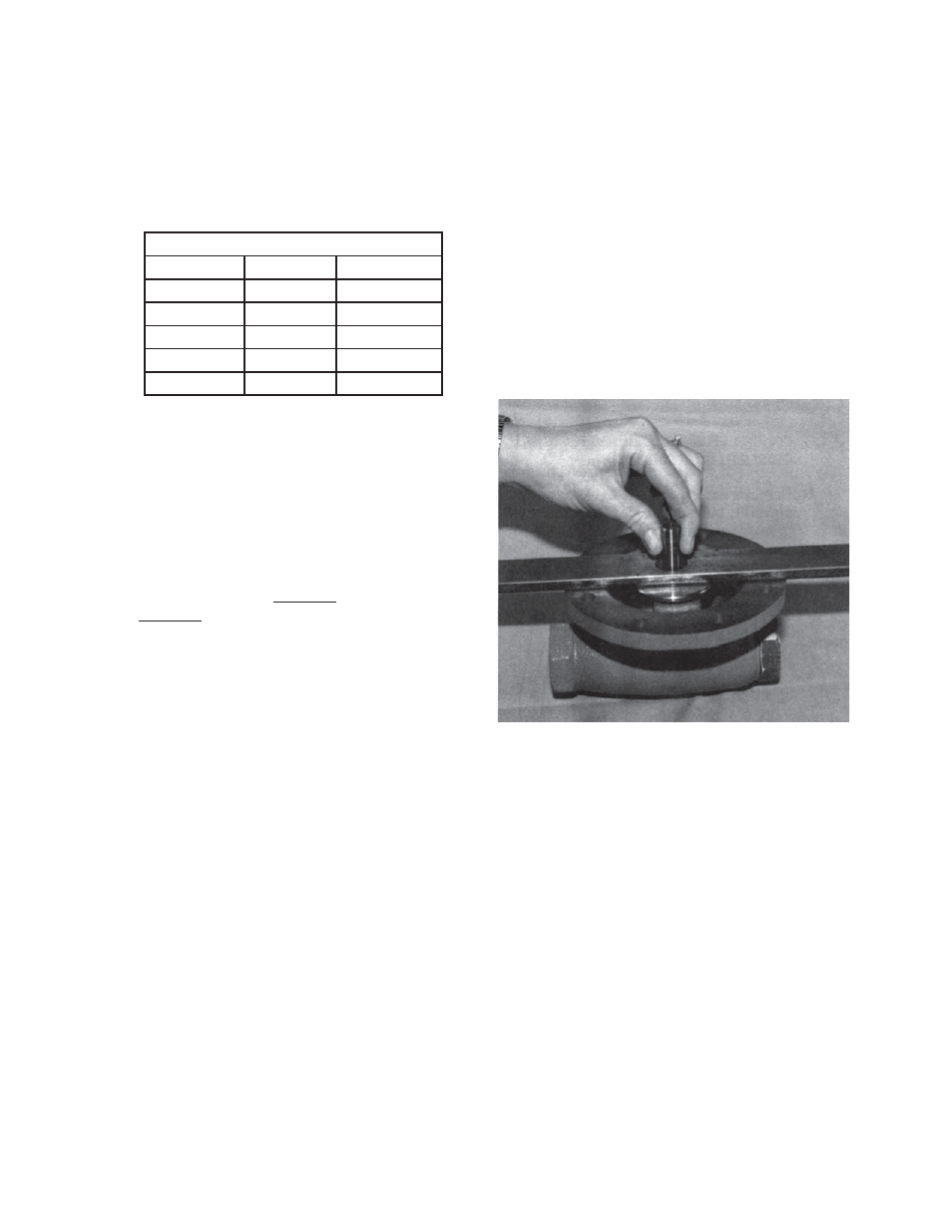
3. Follow procedure "Sub-Section B. Dia-
phragm Re place ment" at the point of
re mov ing diaphragm(s) (20), Step 14. Re-
move di a phragm gasket (19) and pusher
plate stud gasket (12). Obtain a fl at 12" x
1-1/2" x 1/4" plate bar with a 3/4" hole drilled
in the center. Hook the pusher plate stud
(13) into the rocker arm (14) prongs prop er ly.
Pull fi rmly up on the pusher plate stud (13)
to ensure that all slack is removed from the
mechanism and that the piston (24) is seat ed
fi rmly. Relax the pulling and place the fl at bar
over the pusher plate stud (13) with the stud
(13) passing thru the hole of the bar. Again,
pull fi rmly up to re move mech a nism slack.
One of three positions will be reached:
Checking diaphragm setting.
Model 1000HP-5 or -36
Body Size
Bolt Size
Metal Diaph.
1/2"
3/8" Bolt
25 Ft/Lb
3/4"
7/16" Bolt
30 Ft/Lb
1"-1-1/4"
1/2" Bolt
35 Ft/Lb
1-1/2"
9/16" Bolt
45 Ft/Lb
2"
5/8" Bolt
45 Ft/Lb