Caution – Cashco 1000 HP Basic User Manual
Page 4
4
IOM-1000HP-Basic
3. Paint or embed a match mark between body
casting (1) and spring chamber casting (2)
along fl anged area.
4. Remove all diaphragm nuts (9) and bolts (8).
Remove nameplate (28).
5. Remove spring chamber (2), range spring
(27) and spring button (4).
NOTE: The text hereafter will refer to “pusher
plate and stud" (13)" as a single part, for
1/2" – 1-1/4" sizes (DN15-DN32), and as two
sep a rate parts, the “pusher plate (5)” and a
“push er plate stud" (13)” for sizes 1-1/2"
and 2" (DN40 & DN50).
6. Pry up the diaphragm(s) (20) and diaph-
ragm gasket (19) around the perimeter of
the body (1) diaphragm fl ange to ensure
that the diaphragm(s) (20) are not “sticking”.
(Dia phragm gasket (19) is not used with a
com po si tion (soft) diaphragm.)
7. Remove the diaphragm sub-assembly by
slid ing the pusher plate and stud (13) and
nut (11) in the direction of the regulator's
inlet, ap prox i mate ly 1/2"-3/4" (12-20 mm).
The push er plate and stud (13), stud nut (10),
and stud collar (16) should disengage with
the rocker arm (14) slot. Lift vertically for the
diaphragm sub-assembly re mov al.
8. Place the pusher plate stud (13) in a sepa rate
vise, gripping the stud (13) on the hex ago nal
cast-in-place edges located on the un der-
neath side of the pusher plate stud. NOTE:
Do not remove the stud nut (10), stud collar
(16) and the location locking cotter pin (15).
Loosen and remove nut (11).
9. Remove pressure plate (3) by lifting.
10. Pry loose pusher plate and stud (13) from
diaphragm(s) (20) or from pusher plate gas-
ket (12). (Pusher plate gasket (12) is not
used with a composition (soft) diaph ragm.)
Remove the diaphragm(s) (20).
11. Remove pusher plate gasket (12) from
push er plate and stud (13).
12. Clean gasket sealing surface of pusher plate
and stud (13) thoroughly.
13. Install new pusher plate gasket (12), if re-
quired, over pusher plate and stud (13).
14. Install new diaphragm(s) (20) over pusher
plate and stud (13). NOTE: Refer to the quan-
tity of diaphragms (20) incorporated per the
bill of materials listing. Depending on outlet
pressure level, various quantities of metal
diaphragms will be “stacked”.
15. Inspect pressure plate (3) to ensure no
de for ma tion due to over-pressurization. If
de formed, bent, or otherwise distorted, re-
place.
16. Ensuring that the curved outer rim of the pres-
sure plate (3) rests against the dia phragm (20)
directly, place the pressure plate (3) over the
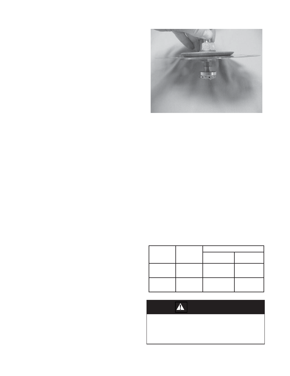
pusher plate and stud (13). Place nut (11)
onto the stud (13) and tighten. Rec om mend ed
torques are as follows:
Diaphragm sub-assembly consists of items (10), (11), (12),
(13), (15), (16) and (20). (Metal diaphragm de sign).
CAUTION
(DO NOT USE FIN GERS TO HOLD DI A PHRAGMS
(20) DURING TIGHT EN ING OF NUT (11).) Use two
fl ange bolts (8) to keep multiple di a phragms (20) bolt
holes prop er ly aligned while tight en ing the stud nut
(10).
Body
Size
Brass Trim
Metal/Comp
Diaphragm
Stainless Trim
Metal
Diaphragm
Comp.
Diaphragm
1/2"
3/4" – 1-1/4"
1-1/2" & 2"
25-30 ft-lbs
35-45 ft-lbs
50-60 ft-lbs
45-50 ft-lbs.
45-50 ft-lbs.
80-90 ft-lbs.
25-30 ft-lbs.
35-45 ft-lbs.
50-60 ft-lbs.
DN15
DN20-DN32
DN40-DN50
34-41 N-m
47-61 N-m
68-81 N-m
61-68 N-m
61-68 N-m
108-122 N-m
34-41 N-m
47-61 N-m
68-81 N-m