Cashco DAP User Manual
Page 2
IOM-DAP
2
d. For condensable vapors (i.e. steam) slope the
external sensing line downward 2 to 5 de grees
to outlet piping to prevent water pock ets, which
allows the diaphragm chamber to always be
self draining. The external sensing line may
be sloped upward for liquids or gases.
5. The
loading
fl uid MUST be the same basic
fl uid as the fl uid passing thru the regulator
body.
1. When a loading pressure – P
Load
– is applied to
the top side of the piston (77), the outlet con trolled
pressure – P2 – will balance at ap prox i mate ly
0.96–.98 of the loading pressure - P
L
. (NOTE:
Fluctuations in P1 – Inlet Pressure will cause a
deviation in P2 – Outlet Pressure due to inverse
sympathetic ratio effect.) See Section VIII.
2. Movement occurs as pressure variations register
on the underneath side of the piston (77). The reg-
is ter ing pres sure is the outlet, P2, or down stream
V. STARTUP
1 Start with the block valves closed.
2. Adjust the loading system pressure control device
so that the main valve is trying to be controlled at
0 psig pressure.
3. If it is a “hot” piping system, and equipped with
a bypass valve, slowly open the bypass valve
to preheat the system piping and to allow slow
ex pan sion of the piping. Ensure proper steam
trap operation if installed. Closely monitor outlet
(down stream) pressure via gauge to ensure not
over-pressurizing. NOTE: If no bypass valve is
in stalled, extra caution should be used in starting
up a cold system; i.e., do everything slowly.
4. Crack open the outlet (downstream) block valve
to approximately 10% full open.
5. Slowly open the inlet (upstream) block valve to
about 25% open. Adjust the loading system pres-
sure control device setpoint pressure upwards
until the regulator is fl owing. Observe the outlet
pressure gauge to ensure not overpressurizing.
6. Continue to slowly open the inlet (upstream) block
valve until fully open.
7. Continue to slowly open the outlet (downstream)
block valve, especially when the downstream pip-
ing system isn’t pressurized. If the outlet (down-
stream) pressure exceeds the desired pres sure,
close the inlet block valve and go to Step 2. Close
bypass valve approximately 25%, and re peat pro-
ce dure.
8. When
fl ow is established steady enough that the
outlet (downstream) block valve is fully open, begin
to slowly close the bypass valve if installed.
pres sure. The loading pressure fl uid op pos es
piston movement. As out let pres sure drops, the
loading pressure push es the piston down, opening
the port; as out let pres sure in creas es, the piston
pushes up and the port opening closes.
3. A complete piston dynamic seal failure will cause
the reg u la tor to fail closed. A loss of loading pres-
sure while inlet pressure is im posed will cause
valve to fail closed.
SECTION IV
IV. PRINCIPLE OF OPERATION
SECTION V
CAUTION
DO NOT HYDROSTATIC TEST THROUGH AN IN STALLED
UNIT; ISOLATE REGULATOR FROM TEST. The pressure
level on the name plate is the rec om mend ed “upper op er -
at ing limit”. High er pres sures could cause in ter nal dam age.
In ad di tion, note on the name plate that the Inlet and Outlet
pres sure and tem per a ture ratings are at different levels.
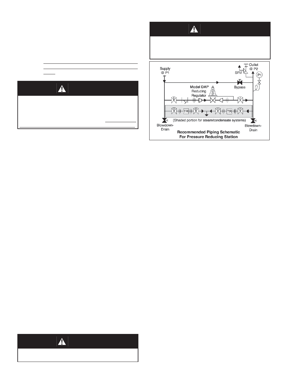
CAUTION
Installation of adequate overpressure pro tec tion is recom-
mended to pro tect the reg u la tor from over pres sure and
all down stream equip ment from dam age in the event of
regulator failure.
CAUTION
Do not walk away and leave a bypassed reg u la tor unat-
tended!