Fluid Components International MT86_MT86HT Manual Operation User Manual
Page 8
FLUID COMPONENTS INTL
CHAPTER 3 - OPERATION
Models MT86, MT86HT
3 - 8
Doc. No. 003162 Rev. F
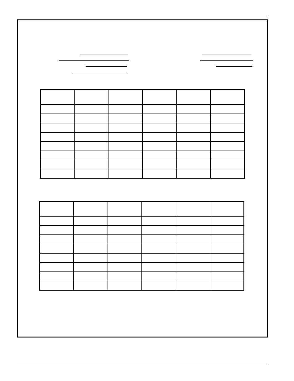
A/D DATA SHEET
SERIAL NUMBER_______________
DATE_______________
SERVICE ____________________ _
UNIT________________
FLOW RATE/LOAD _____________
COMPANY___________
OUTPUT (mA) _________________ (TOTAL OUTPUT)
SENSOR
POINTS
DIS
mA
TP9-10
R. VDC*
A/D**
1
2
3
4
5
6
7
8
SENSOR
POINTS
DIS
mA
TP9-10
R. VDC*
A/D**
1
2
3
4
5
6
7
8
* R. VDC is the reference voltage measured at the individual connectors from points numbered 2(-) to number 3 (+).
** A/D will be calculated at FCI with the above information.
Close dip switch 3 at SW1 (for manual operation) then dial the head selector, SW2, to the desired flow element.
Figure 3-4. A/D Data Sheet
See also other documents in the category Fluid Components International Equipment:
- FC88 KIT (5 pages)
- Quality Assurance Manual (94 pages)
- 8-66B_12-64B Series Manual Installation (4 pages)
- 8-66B_12-64B Series Manual Operation (2 pages)
- 8-66B_12-64B Series Manual Maintenance (2 pages)
- 8-66B_12-64B Series Manual Troubleshooting (4 pages)
- 8-66B_12-64B Series Manual Guide (4 pages)
- 8-66B_12-64B Series Manual Cover Page (10 pages)
- 8-66B_12-64B Series Manual General Information (2 pages)
- 8-66B_12-64B Series Manual Drawings (2 pages)
- 8-66B_12-64B Series Manual Glossary (2 pages)
- 8-66B_12-64B Series Manual CE Conformance (2 pages)
- FLT Series (65 pages)
- FLT93 (12 pages)
- FLT Series Rack Mount (61 pages)
- FLT93 Nuclear (58 pages)
- FR73B Manual Installation (2 pages)
- FR73B Manual Operation (2 pages)
- FR73B Manual Maintenance (2 pages)
- FR73B Manual Troubleshooting (4 pages)
- FR73B Manual Cover Page (10 pages)
- FR73B Manual General Information (2 pages)
- FR73B Manual Drawings (2 pages)
- FR73B Manual Glossary (2 pages)
- FR73B Manual Customer Service (4 pages)
- FR73B Complete Manual (20 pages)
- FS10 Button Setup Quick Guide (4 pages)
- FS10 Field Quick Setup Mode (1 page)
- FS10A (54 pages)
- LS2000 (12 pages)
- OEM MASS FLOW SWITCH (2 pages)
- RF83 Manual Customer Service (4 pages)
- RF83 Manual Glossary (2 pages)
- RF83 Manual Drawings (10 pages)
- RF83 Manual General Information (2 pages)
- RF83 Manual Cover Page (10 pages)
- RF83 Manual Installation (4 pages)
- RF83 Manual Operation (4 pages)
- RF83 Manual Maintenance (2 pages)
- RF83 Manual Troubleshooting (6 pages)
- CMB (106 pages)
- CMF Series Manual Installation of Flow Element (9 pages)
- CMF Series Manual Installation of Electronics (14 pages)
- CMF Series Manual Table of Contents (3 pages)
- CMF Series Manual Technical Data (10 pages)