Burkert Type S039 User Manual
Page 6
20
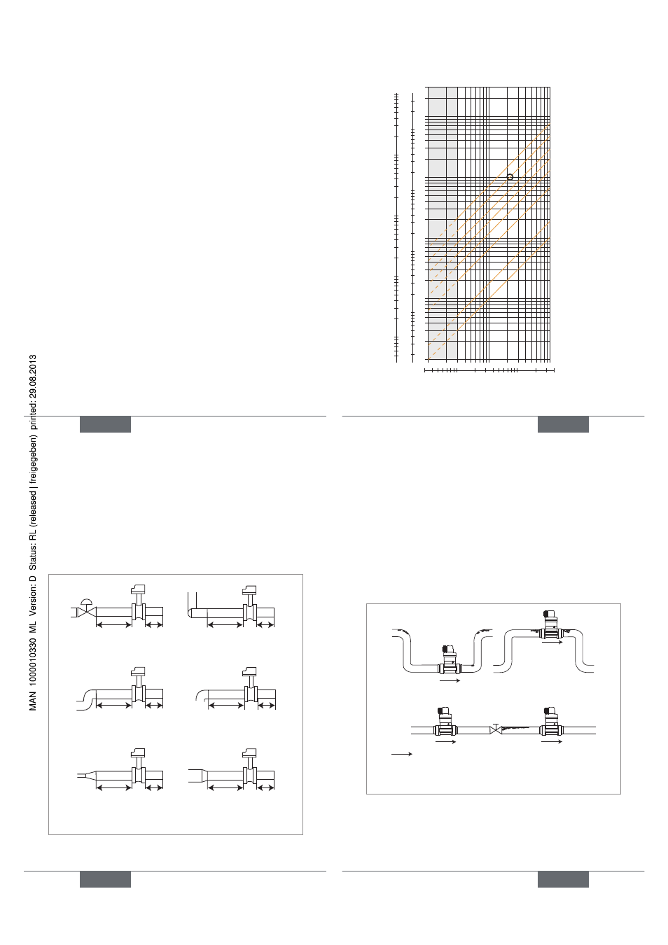
The graph is used to determine the DN of the pipe and the
fitting appropriate to the application, according to the fluid
velocity and the flow rate.
Selection example:
• Specification: if the nominal flow is 10 m
3
/h, the dimen-
sioning of the optimal flow rate must be contained in 2
to 3 m/s
• Answer: on the chart, the intersection of flow rate and
flow velocity gives the appropriate diameter, DN40.
English
21
DN50
DN40
DN32
DN25
DN20
DN15
DN08
DN06
flow rate
Fluid velocity
0.1
0.3 0.5
1
3
5
10
0.01
0.02
0.05
0.1
0.2
0.5
1
2
5
10
20
50
100
200
m
3
/h
0.2
0.5
1
2
5
10
20
50
100
200
500
1000
2000
3000
l/min
0.3 0.5
1
3
5
10
30
m/s
fps
gpm
0.05
0.1
0.2
0.5
1
2
5
10
20
50
100
200
500
1000
English
21
22
→
Install the fitting on the pipe to comply with the
upstream and downstream distances defined by
standard EN ISO 5167-1 (see Fig. 3).
50 x DN 5 x DN
40 x DN 5 x DN
25 x DN 5 x DN
20 x DN 5 x DN
18 x DN 5 x DN
15 x DN 5 x DN
With control valve
Pipe with 2 elbows
at 90°
Pipe with 2 elbows at 90°
in 3 dimensions
Pipe with 1 elbow at 90°
or 1 T-piece
With pipe expansion
With pipe reduction
Fig. 3: Upstream and downstream distances depending
on the design of the pipes.
English
23
→
Use a flow conditioner, if necessary, to obtain the best
accuracy.
→
Prevent the formation of air bubbles in the pipe (see
Fig. 4).
→
Ensure the pipe is always filled with liquid (see Fig. 5).
Correct
Correct
Incorrect
Incorrect
Direction of fluid flow
Fig. 4: Additional recommendations on installation
English
23