Conformity to the pressure directive, General technical data, Diameters available – Burkert Type S039 User Manual
Page 4: Materials, Dimensions
12
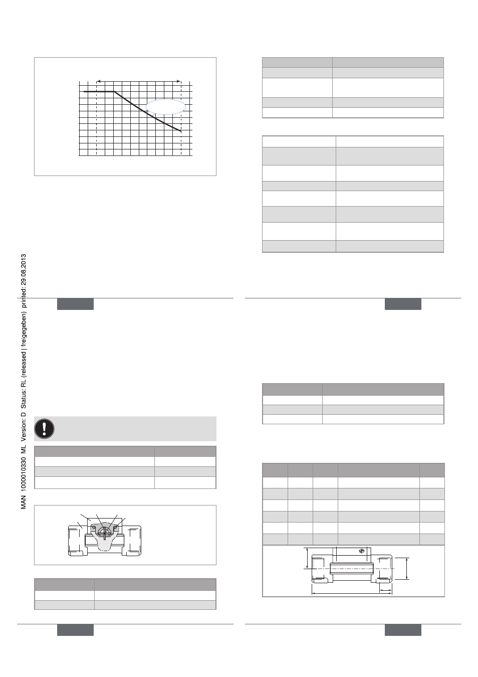
Fluid temperature
Fluid pressure
-10 +10 +30 +50 +70 +90 +110
0
2
1
3
4
5
6
7
8
9
10
11
A
bar
PVDF (PN 10)
°C
Fig. 1: Fluid pressure / temperature dependency curve
for fittings S039 used on their own
conformity to the pressure
directive
The S039 fitting complies with article 3 of §3 from 97/23/
CE directive.
Acc. to the 97/23/CE pressure directive, the device can
only be used in the following cases (depending on max.
pressure, pipe diameter and fluid):
English
13
type of fluid
conditions
Fluid group 1 § 1.3.a only DN ≤ 25
Fluid group 2 § 1.3.a DN ≤ 32
or DN > 32 and PNxDN ≤ 1000
Fluid group 1 § 1.3.b PNxDN ≤ 2000
Fluid group 2 § 1.3.b DN ≤ 200
General technical data
Max. Fluid viscosity
300 cSt
Type of fluid
Clean, neutral or slightly aggressive
Rate of solid particles in
the fluid
max. 1 %
Max. particle size
0,5 mm
Measurement range of
the flow rate in the pipe
0,3 to 10 m/s
Accuracy, with standard
K factor
± (1 % of the full scale* + 3 % of the
measured value)
Linearity
≤ ±
1 % of the full scale (10 m/s)*
Repeatability
±
0,4 % of the measured value*
* determined in the following reference conditions: medium =
water, water and ambient temperatures 20 °C, min. upstream and
downstream distances respected, appropriate pipe dimensions.
English
13
14
diameters available
The diameters available depend on the design of the S039
fitting.
Refer to the graph on page 20 to determine the
appropriate DN of the pipe and fitting.
Connections of the S039 fitting
DN available
External threads, G or metric
DN06
External threads, G or NPT
DN08
Internal threads, G or NPT
DN15 to DN50
materials
Sensor holderPaddle-wheel Axis
Seal
Body
Fig. 2: Sectional drawing of the S039 fitting
Component
Material
Seal
FKM or EPDM
Body
Brass (CuZn39Pb2)
English
15
Component
Material
Screws
Stainless steel (316L - 1.4404)
Paddle-wheel
PVDF
Shaft and bearings
Ceramics (Al
2
O
3
)
dimensions
Table 1: Dimensions of the fittings with G or NPT
internal thread connections
DN
[mm]
P [mm] A [mm] D [inch]
L [mm]
15
34,5
90,0
G 1/2 or NPT 1/2
16,0
20
32,0
94,0
G 3/4 or NPT 3/4
17,0
25
32,2
104,0
G 1 or NPT 1
23,5
32
35,8
119,0
G 1 1/4 or NPT 1 1/4
23,5
40
39,6
129,0
G 1 1/2 or NPT 1 1/2
23,5
50
45,7
148,5
G 2 or NPT 2
27,5
A
L
D
P
English
15