Description of icons and leds, English – Burkert Type 8076 User Manual
Page 31
31
Adjustment and commissioning
Type 8026- 8036- 8076
8.6.
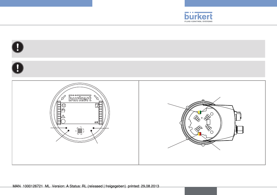
Description of icons and leDs
• The LEDs of the display module are duplicated on the electronic board that is located under the display module: these LEDs
become visible when the device is not equipped with the display module.
• The yellow LED related to a transistor output is deactivated if the transistor output is configured in pulse mode ("Pulse").
The LEDs of the display module are duplicated on the electronic board that is located under the display module: these LEDs become
visible when the device is not equipped with the display module.
OP
EN
LO
CK
flow_l
600.0l/h
flow_m3
0.60/h
ERR
Red LED: shows
an error.
not used
Yellow LED: shows that transis-
tor 1 is switched
Yellow LED: shows that transistor 2
is switched
Red LED: shows an error.
Yellow LED: shows that
transistor 2 is switched
Green LED: shows that
the device is energized
Yellow LED: shows that
transistor 1 is switched
Fig. 28: Position of the icons and description of the LEDs
English