Burkert Type 8076 User Manual
Page 19
19
Installation and wiring
Type 8026- 8036- 8076
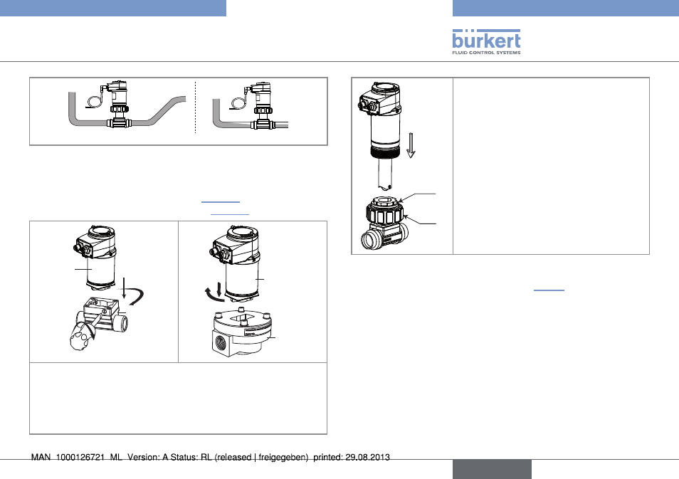
Correct
Incorrect
Fig. 12: Air bubbles within the pipe / Filling of the pipe
→
Fit the display module (see related operating manual) to para-
meter the device.
→
SE36
S030
1
2
3
SE36
S070
1
2
→
1 : Insert the electronic module in the sensor holder.
→
2 : Turn the electronic module by a quarter turn.
→
3 : Secure the electronic module and the S030 fitting only, by
tightening the screw with a suitable tool to a max. tightening
torque of 1 Nm.
Fig. 13: Assembling the SE36 and the fitting S030 or S070
A
B
→
Check that there is a seal on the fitting
and that it is not damaged. Replace the
seal if necessary.
→
Place nut A on the fitting and insert
circlip B into the groove.
→
Carefully insert the device into the
fitting. If assembly is correct, the device
can no longer rotate on itself.
→
Secure the unit with nut A, tightening
only by hand.
Fig. 14: Installation of flowmeter 8026 into the fitting S020
→
Set the K factor parameter (see chap. „8.8.8“) or have it deter-
mined through a teach-in procedure.
English