English – Burkert Type 1094 User Manual
Page 13
1094 - 11
english
5 OPERATION AND FUNCTION
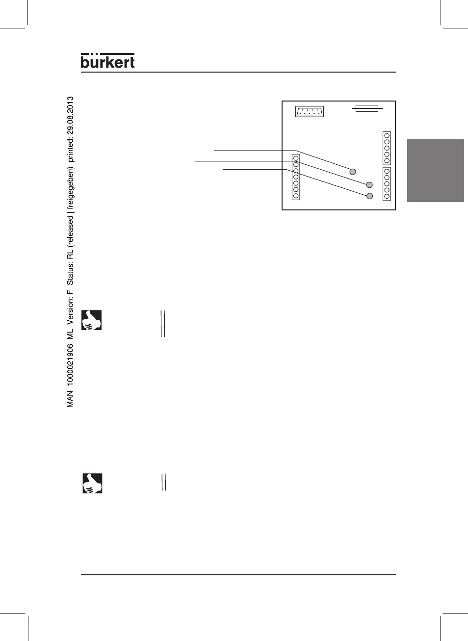
5.1 Display elements
The controller has 3 red LEDs
For the display of
• „Proportional valve active“
• „Pump motor active“
• „Supply voltage connected“
In order to set up the controller in a petrol pump, all the components, signal lines and
the gas gauge from the calibration case must be correctly connected.
The operation and calibration of the controller takes place exclusively using the exter-
nal Type MKNE-1094 manual control unit, which is connected to the controller using
a 9-pole SUB-D plug.
The settings that are possible with the manual control unit are described in detail in
the Type MKNE-1094 operating instructions.
5.2 Setting and operation of the controller
5.3 Calibration of the controller
The electronic vapour recovery controller is program-controlled and has to be adapt-
ed (calibrated) to the real petrol pump process before being used for the first time.
The calibration is carried out with the separate (external) MKNE-1094manual control
unit. There is a separate set of operating instructions for this external manual control
unit. Carefully read through these operating instructions and selection the mode of
operation relevant to your application.
5.4 Pulsrate and frequency input
The pulse rate output from the petrol pump computer will be defined by the petrol
pump manufacturer. The output pulse rate can be set up on the controller with the
Type MKNE-1094 manual control unit.
NOTE
In the case of controllers for the two-sided operation of the petrol
pump, a separate SUB-D plug is provided for each side of the petrol
pump (Side A and Side B).
NOTE
Bevore the calibration, the pulse rate, the K-factor and the pump
after-run time must be determined and be entered.