Hsi lg ne replacement of valve seat – Burkert Type 2712 User Manual
Page 16
M
AINTENANCE
AND
S
ERVICING
OF
THE
V
ALVE
14 - 2712
hsi
lg
ne
Replacement of valve seat
The drive unit must be completely removed to replace the valve seat.
Disassembly
Remove the electrical and pneumatic supplies from the Top
Control.
Pull off the pneumatic hose between Top
Control and drive unit at control connection of drive unit.
In the case of control function A, pressurize the lower control connection of the drive unit with
compressed air (5 to 7 bar) so that the control cone lifts from the valve seat and is not damaged. With
control function B, no compressed air must be applied for this purpose.
Remove the drive unit in the open valve position by unscrewing the threaded nipple of the housing.
Before reinstalling the drive (in open valve position), grease the nipple thread with stainless steel
lubricant, e.g. silicone grease CKS 1110 from OKS, Munich and replace the graphite seal.
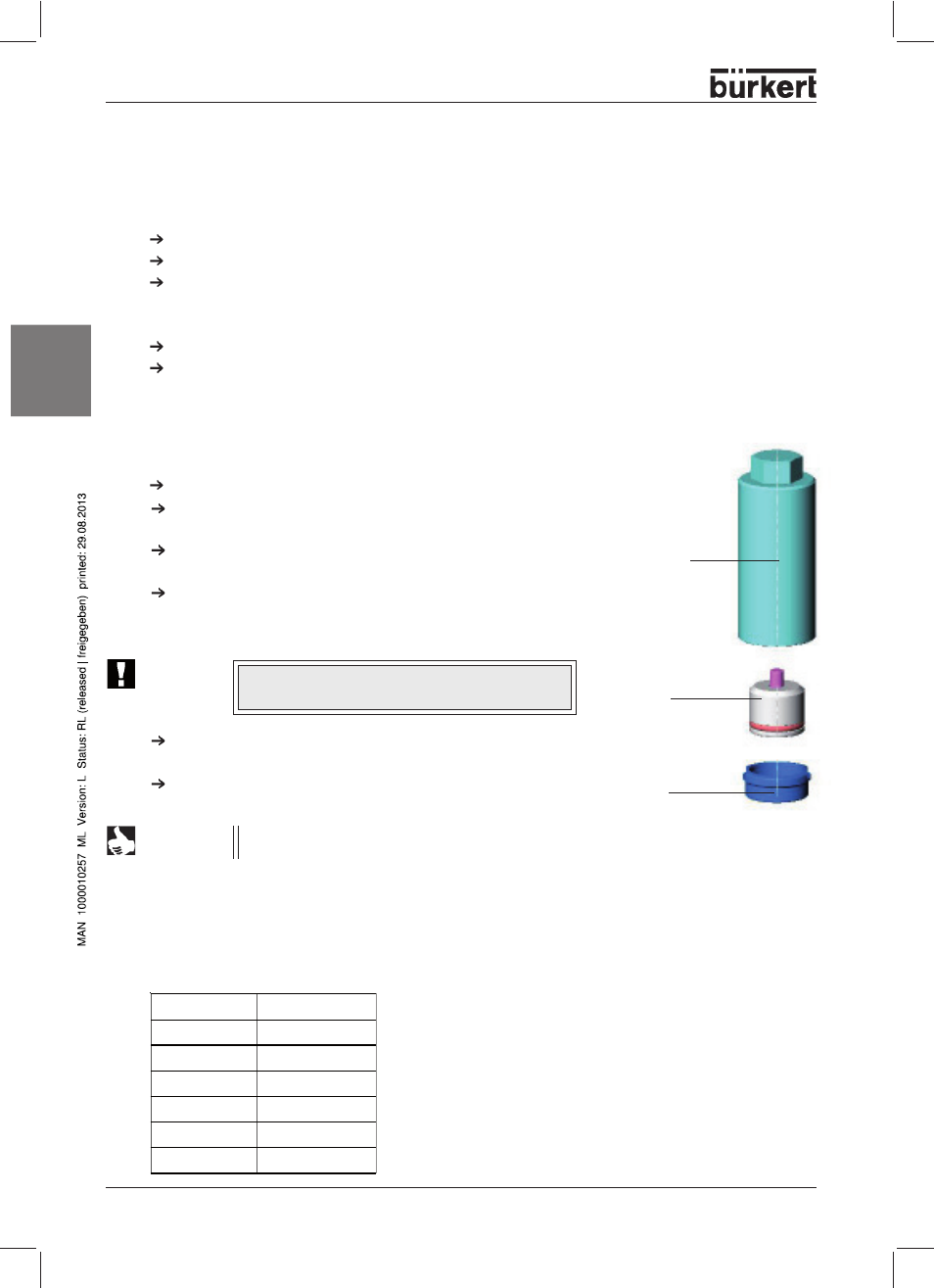
Assembly tool
Tool insert
(depending on nomi-
nal diameter of seat)
Valve seat
Replacement of valve seat
Unscrew the old housing seat using the assembly tool and a
spanner.
Clean thread and sealing surface in the housing with
compressed air.
Select a tool insert and screw it into the assembly tool.
Push the new seat onto the assembly tool, grease the thread
with stainless steel lubricant, e.g. Klüberpaste UH1 96-402
from Messrs. Klüber.
Place the attached seat by hand into the housing thread and
screw it in.
Tighten the seat with a torque wrench to the torque specified.
ATTENTION!
For special applications such as for oxygen and
analysis, use only the approved lubricants.
NOTE
On installing a valve seat with a different nominal
diameter, the order number for the valve changes!
Assembly
Assembly is carried out in the reverse sequence to
disassembly.
Housing DN
Order no.
15
652 604
20
652 605
25
652 606
32
652 607
40
652 608
50
652 609
Seat assembly tools