Burkert Type 2101 User Manual
Page 3
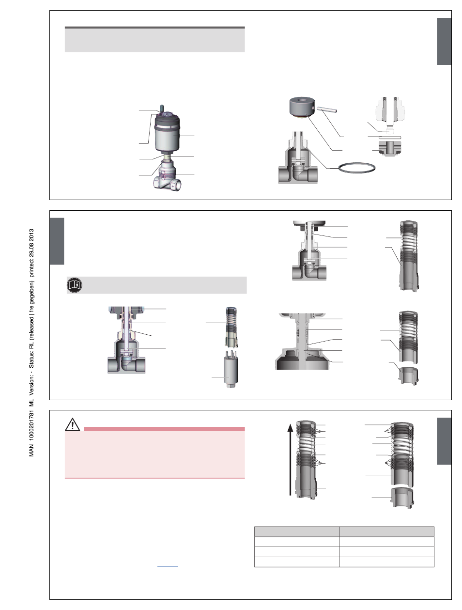
note!
Damage to the seat seal or the seat contour!
• When removing the actuator, ensure that the valve is in open
position.
→
Control function A pressurize the pilot air port 1 with compressed
air (5 bar): valve opens.
→
Using a suitable open-end wrench, place the wrench flat on the
tube.
→
Unscrew the actuator from the valve body.
Actuator
Nipple
Valve body
Air discharge connection
CFA, CFB
Pilot air port
CFI
Pilot air port
CFA, CFB, CFI
Flats for open-end
wrench
Release bore
2
1
Removing the swivel plate:
→
Knock out the pin with a suitable pin punch.
Pin punch ø 3 mm, for spindle diameter 10 mm on the swivel
plate.
Pin punch ø 5 mm, for spindle diameter 14 mm on the swivel
plate.
Pin punch ø 6 mm, for spindle diameter 22 mm on the swivel
plate.
→
Remove swivel plate.
Spindle
Pin
Swivel plate
Graphite seal
english
→
Unscrew the spindle guide with the aid of the installation wrench
1)
and an open-end wrench (series production status up to January
2013).
→
Unscrew the spindle guide with the aid of a modified socket
wrench
1)
(series production status since January 2013).
SP22:
→
Unscrew the VA spindle guide with the aid of an open-end wrench.
1)
The installation wrench or modified socket wrench is
available from your Bürkert sales office.
Installation wrench
Packing gland
Spindle guide
Spindle
Packing gland tube
Series production status
up to January 2013
Packing gland
Spindle guide
Spindle
Packing gland tube
Series production status since
January 2013
SP10 / SP14
Packing gland
Spacer
Spindle
Packing gland tube
SP22
VA spindle guide
english
WArnInG!
Risk of injury from parts jumping out!
When the spindle opening is exposed, the individual parts of the
packing gland are pressed out at an undefined speed when the
pilot air ports is pressurized.
• Before pressurizing with control air, safeguard the ambient area of
the discharge opening (e.g. place spindle on a firm base).
→
Control function A and I Pressurize pilot air port 1 with 6 – 8
bar.
→
Control function B Pressurize pilot air port 2 with 6 – 8 bar.
→
Grease the individual parts of the new packing gland with the
supplied lubricant.
→
Connect the individual parts to the spindle in the specified
direction and sequence.
→
Push packing gland into the packing gland tube.
→
Screw spindle guide / VA spindle guide back in using the instal-
lation tool. Observe torque (see “Tab. 3”).
Support ring
Upper chevron seals
Upper pressure ring
Pressure spring
Lower pressure ring
Lower chevron seals
Spindle guide
Insertion direction
for packing gland parts
Spacer
SP10 / SP14
SP22
VA spindle guide
2
)
Tightening torques of spindle
Spindle diameter
Tightening torque [Nm]
10 mm
6
14 mm
15
22 mm
60
Tab. 3: Tightening torques of spindle
2)
VA spindle guide is not included in the seal set
english