Actuators g-100, h-125 – Burkert Type 2033 User Manual
Page 12
12
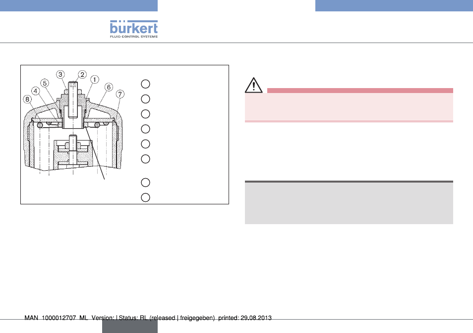
Option: Maximum stroke limitation
7.2.
Actuators G-100, H-125
Loctite 274
Parts required
1 Threaded nipple
2 Setscrew M12 x 1.5
3 Nut M12 x 1.5
4 Nut
5 O-ring (actuator)
6 Acutator cover
(actuator)
7 Sleeve (actuator)
8 Disk (actuator)
Fig. 4: Actuators G-100, H-125,
maximum stroke limitation without position repeater
7.2.1. Work to be carried out before
installation
DANGER!
Hazard due to high pressure!
• Interrupt the control air and fluid infeed before modifying the
devices and reduce the pressure in the fluid system.
→
Interrupt supplies of control air and medium.
→
Empty valve housing.
→
Unscrew transparent cap from actuator cover
⑥.
→
Screw out position indicator with Allan key (WAF8).
NOTE!
Damage to the actuators due to incorrect tool!
• Only the special wrench provided by Bürkert for the purpose
must be used to screw down the actuator cover.
• (see chapter on assembly accessories).
→
Screw off actuator cover
⑥ with special wrench, counterbracing
at the sleeve.
english
Type 2000, 2002, 2012
2030, 2031; 2032, 2033