Alliance Laundry Systems PHM1397C User Manual
Page 44
© Published by permission of the copyright owner – DO NOT COPY or TRANSMIT
Specifications and Dimensions
F8112101
42
Making Connections to Machine
After electrical service feeder has been installed and
electrical service voltage verified by a volt meter,
follow this procedure to connect service to the
equipment.
1. Remove screw securing electrical service
connection panel and remove panel from
machine.
2. Install an appropriate strain relief or conduit
connector in cover.
3. Feed wire through connector leaving about 6 in.
(150 mm) pigtails on inside of cover. Strip about
3/8 in. (10 mm) insulation off the end of each
wire.
4. Tighten strain relief or conduit connector in
place.
5. Connect ground wire to ground terminal at
electrical service connections on machine.
6. Connect L1, L2 and L3 to terminal block
provided at electrical service connections on
machine.
7. Reinstall panel onto rear of machine and tighten
cover screw.
Adjusting Control Transformer Taps
Adjust control transformer to deliver correct voltage to
machine controls.
1. Measure line-to-line voltage to be supplied to
machine with a volt meter.
2. Refer to the schematic supplied with machine
and locate transformer terminal chart.
3. In this chart, locate the primary voltage range,
which corresponds to line voltage measured
above, and note terminals which would be used
on primary.
4. In the chart, locate the secondary terminals
corresponding to line voltage. If line voltage is
not in chart, round it up to the next higher
voltage, which is in the chart, or contact a service
technician for assistance.
5. Remove two screws holding rear electrical
enclosure in place and remove rear electrical
enclosure cover.
6. Locate control transformer in enclosure – the
primary is on the right of the transformer and the
secondary terminals are on the left. Make sure
terminals are connected to primary and
secondary terminals selected in steps 3 and 4.
7. Power up machine temporarily and, using a volt
meter, verify the voltage on transformer
secondary is between 100 and 130 VAC.
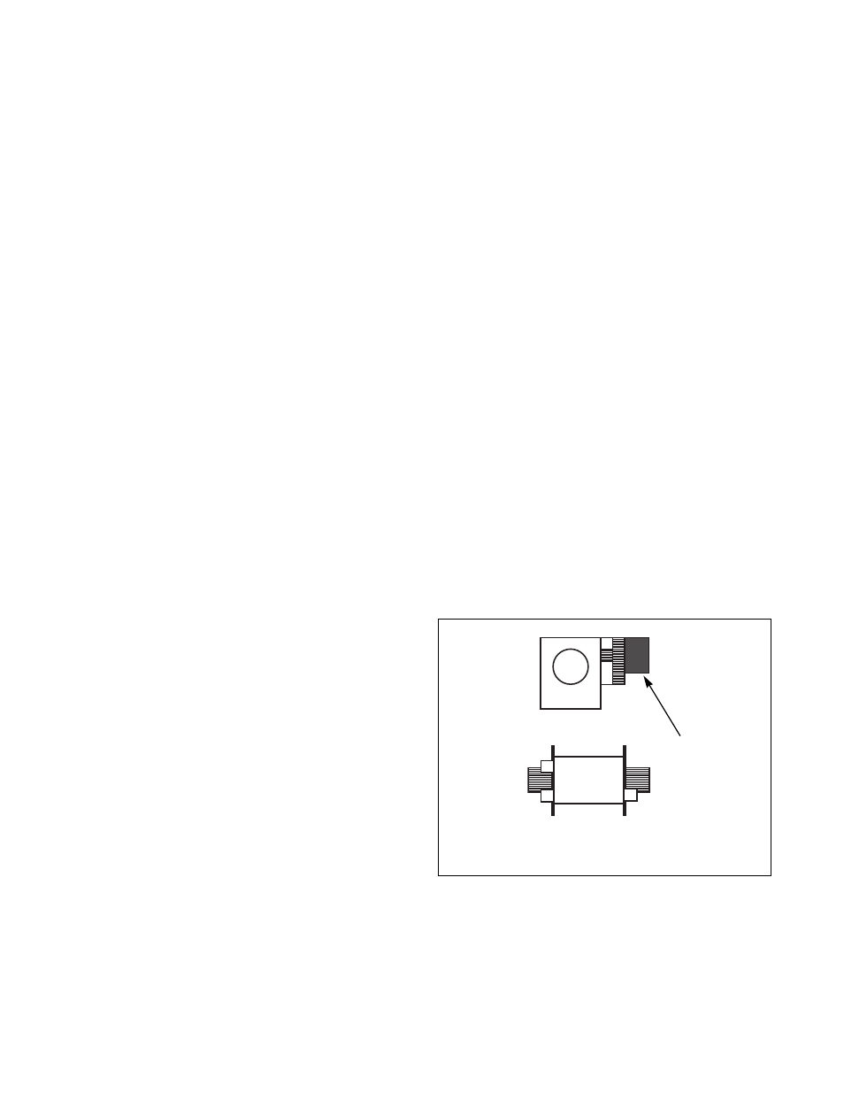
Provisions for 50 Hz Installations
If machine is to be installed on a 50 Hz power system,
adjust control transformer taps as described in
Adjusting Control Transfer Taps section. Then
change drain valve wiring as follows:
1. Disconnect power from machine. Follow lock-
out/tag-out procedures.
2. Remove lower rear panel to access drain valves.
3. Snap black plastic cover off of each drain valve
motor by locating and squeezing two tabs on
each cover.
4. On each drain valve motor there are three
terminals (labeled 60 Hz, 50 Hz and N).
Locate these terminals.
5. On each drain valve motor, move wire from 60
Hz tap to 50 Hz tap. There should be wires on 50
Hz terminal and N terminal.
6. Reinstall black plastic motor covers.
7. Reinstall rear panel.
8. Reconnect power to machine.
NOTE: If the proper tap on drain valve motor is
not selected it will run hot and will be damaged.
PHM695N
1
Cover
Figure 18
50Hz
60Hz
N
1