Brooks, 4800 series – Brooks Instrument 4800 Series User Manual
Page 19
3-1
Brooks
®
4800 Series
Section 3 Operation
Installation and Operation Manual
X-TMF-4800-MFC-eng
Part Number: 541B072AAG
September, 2013
3-1 Operating Procedure
After the MFC/MFM has been properly installed in the process, it is ready
for operation. When initiating flow, slowly open the valve to avoid a flow
surge. Bypass is a help in bringing the flow on smoothly. Avoid starting a
pump to supply the flowmeter without the use of a valve upstream of the
flowmeter.
3-2 Theory of Operation
As with traditional Thermal Mass Flow devices, the 4800 Series flow
measurement system consists of two components: the flow restrictor and
the sensor. The purpose of the 4800 Series flow restrictor is to create
backpressure and force flow through the thermal sensor. Figure 3-1 is a
cross sectional cut-away view depicting gas flow around the thermal
sensor.
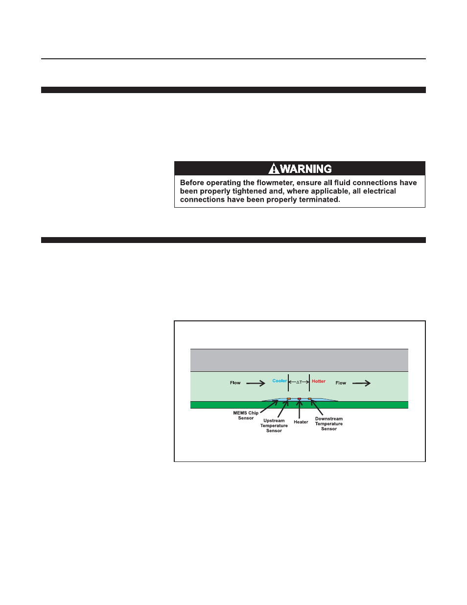
Figure 3-1 Gas Flow Across the MEMS Sensor
The 4800 Series sensor is a Micro Electro Mechanical Systems (MEMS)
based thermal sensor. As shown in Figure 3-1, the gas flows directly
across the MEMS sensor, resulting in extremely fast response times. As
with traditional thermal mass flow sensors, upstream and downstream
temperature sensors are centered around a heating element. As gas flows
across the upstream temperature sensor towards the heater and the
downstream temperature sensor, it cools the upstream temperature sensor
and heats the downstream temperature sensor. This causes the