Flowline LU29-1 EchoSonic II User Manual
Page 14
14 of 24
EchoSonic II
31 MAR 11
MN300610
Rev B
General notes for electrical connections, usage and safety:
Where personal safety or significant property damage can occur due to a spill, the
installation must have a redundant backup safety system installed.
Wiring should always be completed by a licensed electrician.
Supply voltage should never exceed 28 VDC.
The sensor materials must be Chemically compatible with the liquids to be measured.
Design a fail-safe system for possible sensor and/or power failure.
Never use the sensor in environments classified as Hazardous.
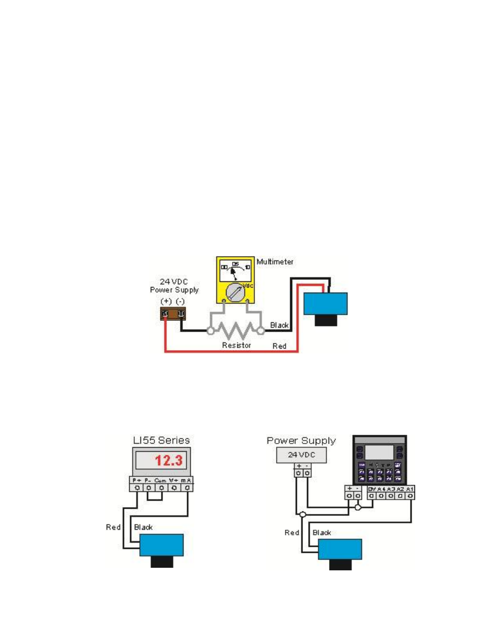
Voltage Output
EchoSonic II can be used as a 0 to 5 or 0 to 10 VDC output device. A resistor will need to be added to the
circuit to enable a voltage output (refer to the wiring diagram below).
0-5 VDC output
o Add a 250 Ohm resistor
o Actual output will be 0.8 to 5 VDC
0-10 VDC output
o Add a 500 Ohm resistor
o Actual output will be 2 to 10 VDC
Wiring to Display, Controllers & PLC’s
Below is a quick review of wiring the EchoSonic II to common display, controllers and PLC’s.
DataView LI55 Series
Level Controller
Commander LI90 Series
Multi-Tank Level Controller