Flowline LU29-1 EchoSonic II User Manual
Page 13
23 MAR 11
EchoSonic II
13 of 24
Rev B
MN300610
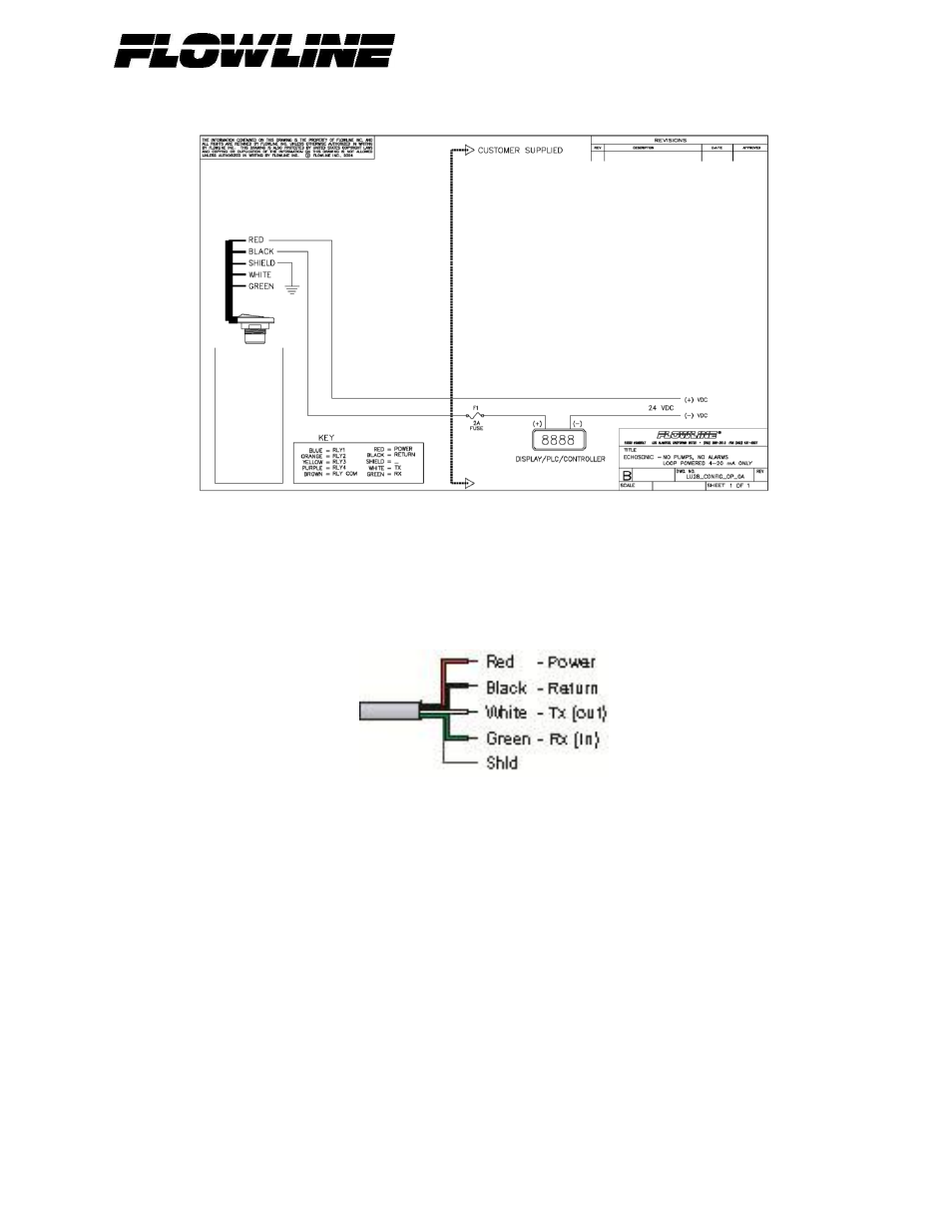
Wiring Diagram
Wiring EchoSonic II
After you have finished positioning and mounting EchoSonic II, follow WebCal’s wiring diagram to wire
EchoSonic II. Flowline recommends using a qualified licensed electrician to wire EchoSonic II and your
application’s components.
Wire Connections:
Red & Black
Red and Black leads are for connection to a 24 VDC power supply or to a 4-20 mA loop power
source. The red and black wires can be extended up to 1,000 feet using a 22 gauge or larger wire,
however do not extend the green and white wires.
White & Green
White and Green leads are reserved for use with WebCal and should not be connected during
usage in the application. These wires should not be connected to WebCal while power is supplied
from any source other than the LI99 series Fob.
Note: Once EchoSonic is configured, isolate the white and green wires from active power to
prevent a short of the configuration circuit.
Note: Do not extend the White & Green wires beyond 15’.