BEI Sensors Encoder Signal Broadcaster Module User Manual
Page 2
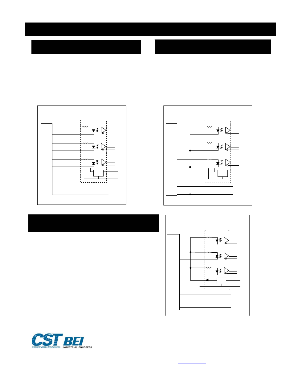
CONNECTION INSTRUCTIONS (for Isolated Circuit and Anti-Dither Functions)
924-02097-001 Rev 3/09
Copyright 2009 by BEI Industrial Encoders, 1-800-ENCODER,
www.beiied.com
-2807
2726
7230 Hollister Avenue, Goleta, California 93117
Tel: 800-350-2727 Fax: 800-960-
A A
A/ A/
B B
B/ B/
Z Z
Z/ Z/
+V
0V
A
A/
B
B/
Z/
Z
+V
0V
REG
VS
0V
Encoder Differential Line Driver Out
Optical Isolator
put
Figure 1
Standard Connection to
Optical Isolator Module
Single Ended Line Driver (See Figure 2)
Differential Line Driver (See Figure 1)
Encoder signal from 5 VDC to 24 VDC (must specify
the voltage when ordering)
Connect broadcaster A to optical isolator module input
channel A, B to B and Z to Z. Connect the A/, B/, and
Z/ inputs of the optical isolator to circuit common of
the encoder supply. Single ended operation is limited
to shorter cable runs and is more susceptible to noise.
Encoder signals from 5 VDC to 24 VDC (must
specify the voltage when ordering)
This is the preferred type of encoder output as it
has the best noise immunity. Connect each
encoder signal to its like input (A to A, A/ to A/,
etc).
A
A
A/
B B
B/
Z Z
Z/
+V
0V
A
A/
B
B/
Z/
Z
+V
0V
REG
VS
0V
Encoder Sin
Optical Isolator
gle Ended Line Driver Output
Figure 2
Connection Diagram
Single Ended Line Driver
Broadcaster
Broadcaster
Broadcaster Module
Encoder
Supply
Open Collector with or without Internal Pull-
up Resistors (See Figure 3)
Encoder NPN (sinking) outputs.
Connect encoder output A to optical isolator module
input A/, B to B/ and Z to Z/. Connect the A, B, and Z
inputs of the broadcaster to the auxiliary output terminal
on the broadcaster module. This connection results in a
logic inversion within the broadcaster module. To
compensate for the logic reversal, swap A for A/, B for
B/, and Z for Z/ at the broadcaster outputs.
A or A/
A
A/
B or B/
B
B/
Z or Z/
Z
Z/
+V
0V
A
A/
B
B/
Z/
Z
+V
0V
REG
VS
0V
Encoder O
Optical Isolator
pen Collector Output
Figure 3
Connec
Open
t
Coll
le
ion Diagram
ector to Optical Modu
Broadcaster
Broadcaster
AUX
5V
Optical Regulation
Power Supply