Module pinout module usb commands, Usb communication protocol – BEI Sensors Dual Encoder to USB Converter Module User Manual
Page 4
Tel:805-968-0782 / 800-350-2727 | Fax: 805-968-3154 / 800-960-2726
7230 Hollister Ave., Goleta, CA 93117 |
www.beisensors.com
Specification No. 02109-001 Rev. 06/11
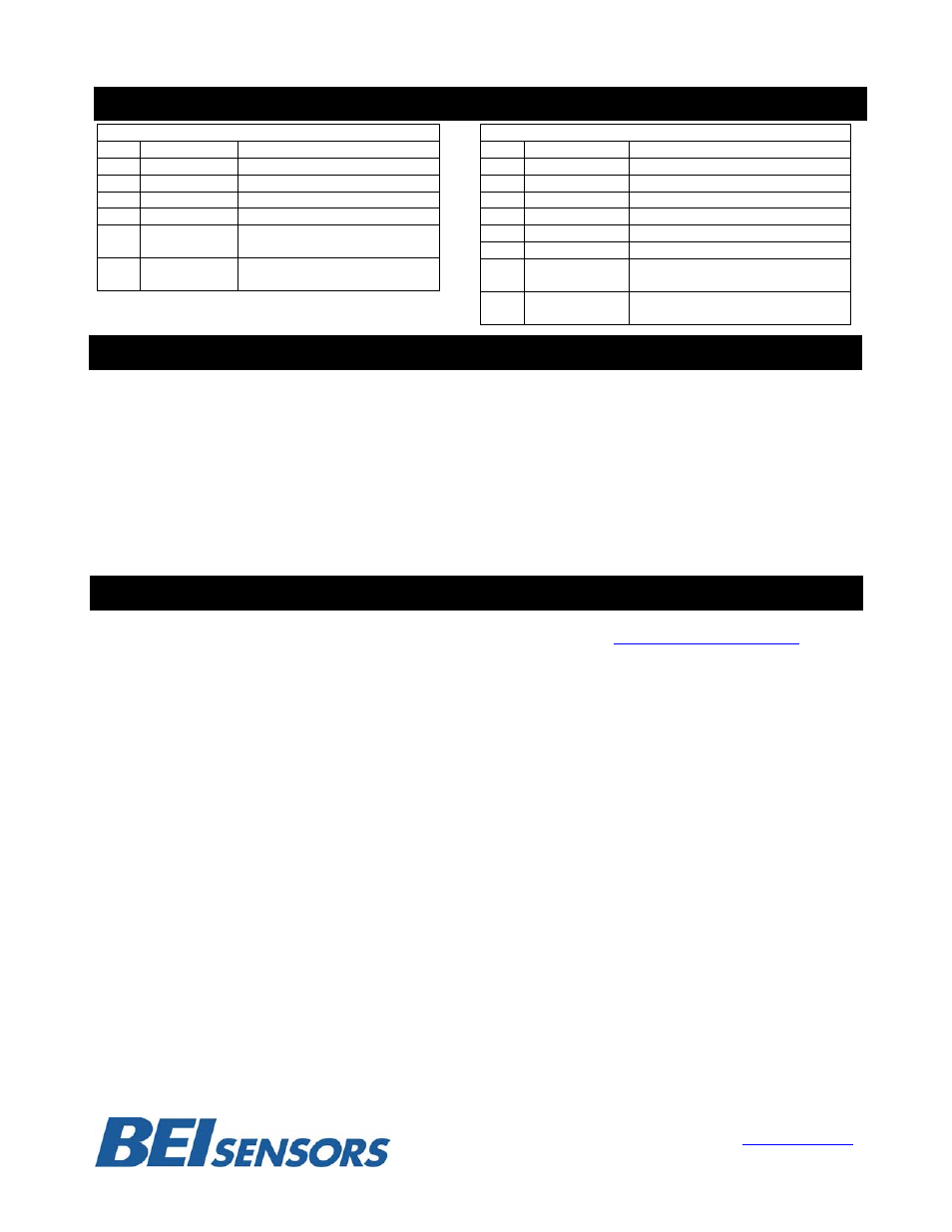
MODULE PINOUT
MODULE USB COMMANDS
ABSOLUTE ENCODER COMMANDS
(see page 4)
Set Data Length of Encoder (8 to 32 bits)
Read
Encoder
Position
GENERAL COMMANDS
(see page 4)
Read module Part Number and Serial Number
INCREMENTAL ENCODER COMMANDS
(see page 3)
Set Encoder Count Mode, Pulse/Dir, X1, X2, X4 and
Counter Width
Set Encoder Counter to Preset/Zero on Z Channel
Trigger
Set Encoder Counter to Value XXXX
Read Encoder Counter Value
Read Encoder Status Flags
USB COMMUNICATION PROTOCOL
Download the appropriate driver package for your operating system from:
and install the USB to serial link drivers. When you plug in the module via the supplied USB cable, you
should notice an additional serial port becomes active on your PC (for example, COM3). You can check
which port it is by going into the device manager in windows (right-click MyComputer, select Properties, go
to Hardware/Device Manager, expand the Ports item.). You can now communicate with the device with any
serial communication program (such as HyperTerminal, which comes with Windows). The serial port
settings are 115200 baud, 8 data bits, no parity bit, 1 stop bit, no flow control.
The general formats of the commands are as follows:
$
Commands that return data will respond according to their command description.
Successful commands that do not return data will respond with an ACK:
*ACK
Unsuccessful commands will respond with a NACK:
*NACK
The dollar sign ($) is the start of packet character. The
specifies the address of the module that the command is intended for (at this time, only address 0 (zero) is
supported). The
being sent, if any. The
designated as UPPER-CASE characters and data fields are designated in lower-case characters.
Absolute Encoder Connections
PIN
Description
Notes
D
Data
Data Line From encoder
D/
Data/
Data/ Line From Encoder
C
Clock
Clock Line From Encoder
C/
Clock/
Clock/ Line From Encoder
V+ +V
+V from external
power supply*
0V
0V (Circuit
common)
Connect 0V from external
power supply
*Not internally connected in Module
Incremental Encoder Connections
PIN
Description
Notes
A
Channel A
Channel A Line From Encoder
A/
Channel A/
Channel A/ Line From Encoder
B
Channel B
Channel B Line From Encoder
B/
Channel B/
Channel B/ Line From Encoder
Z
Channel Z
Channel Z Line From Encoder
Z/
Channel Z/
Channel Z/ Line From Encoder
V+ V+
+V from external
power supply*
0V
0V(Circuit
Common)
0V from external
power supply*