Technical data – Delta Controls DPT-2000 User Manual
Page 14
12 IOM-DPT-A: FEB 2014
4.1.1.
The DPT-2000ALW transmitters in intrinsically safe version have additional designations, which
are specified in DTR.DPT.ALW.03 Appendix Exi.
4.1.2.
The DPT-2000ALW transmitters in Exd version have additional designations, which are specified
in DTR.DPT.ALW.03 Appendix Exd.01.
4.2. Ordering procedure
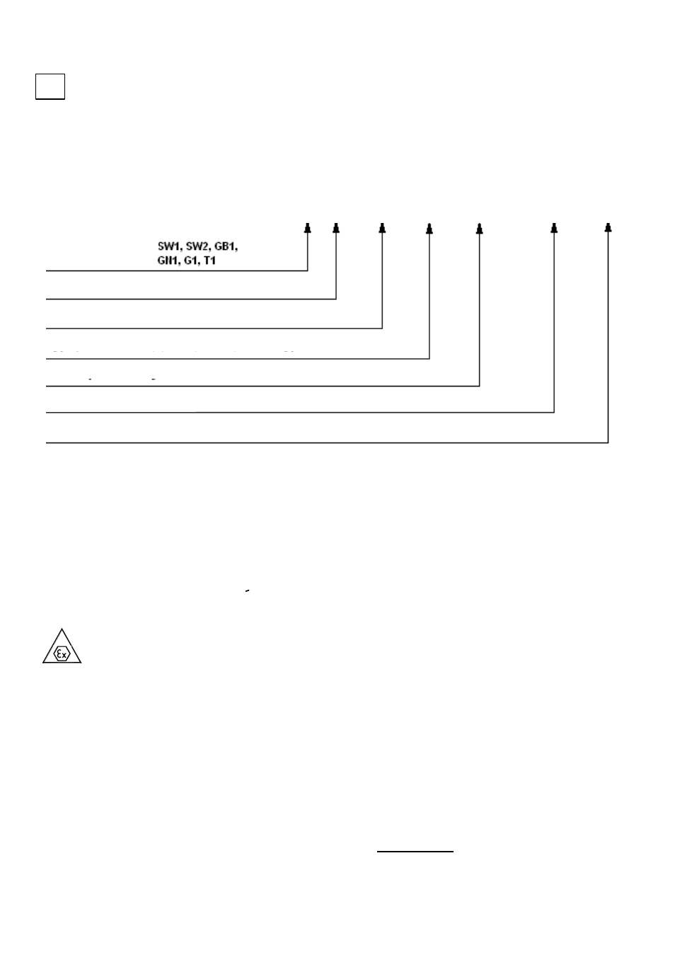
Procedure of ordering
Example: Temperature transmitter DPT-2000ALW, shield T1, version Exi, mounting length 250 mm,
connection flange DN50 PN40, nominal range: -40 do 550 °C, calibrated range: 0 do 300 °C,
alarm signal for example 23 mA.
DPT-2000ALW / T1 / Exi / L=250 mm / DN50 Pn40 / - 40 ÷ 550 °C / 0 ÷ 300 °C / 23 mA.
5. TECHNICAL DATA
5.1. Electrical parameters
Power supply for normal version
12 * ÷ 55V DC
Power supply for intrinsic-safe versions
- in
accordance with „Appendix Exi”
Power supply for Exd versions
- in accordance with
„Appendix Exd.01”
Output signal
4÷20mA + Hart Rev.5.1
Communication
realised via a 4÷20mA signal and Hart transmission
using KAP-03 communicator or SH05 Delta Controls
modem
or PC computer with DPT2000 software
.
Resistance for communication (Hart)
250÷1100
, min 240Ω
Load resistance
Ro[
] =
Load resistance for intrinsic-safe versions
– in accordance with „Appendix Exi”
*) 15 V for transmitters with display backlight
.
i
Usup[V]-12V *
0,023A
Special version: Exi, Exd, IP-67, another
kołnierza
Set (calibrated) range
Type of shield
Mounting length
Connection thread: M20x1,5, G1/2”, M27x2, G1” or flange type
Nominal range
Alarm signal
DPT-20
00ALW/___/___/L=.…mm/___/___÷___°C/___÷___C/___