Communication Concepts 2M 1KW Amateur Application Note User Manual
Page 9
MRFE6VP61K25H MRFE6VP61K25HS 2 Meter Amateur
9
RF Reference Design Data
Freescale Semiconductor
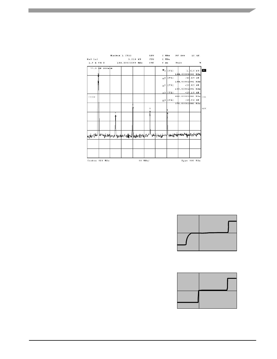
HARMONIC MEASUREMENTS
At the one kW level, second harmonic is --42 dBc, third
harmonic is --32 dBc, and fourth harmonic is --37 dBc.
To be used “on the AIR” this amplifier will likely need a filter
to be compliant with local regulations. A diplexer could give
better results than a simple low pass filter because
harmonics are absorbed in a resistive load instead of being
reflected to the transistor.
at e:
4. NOV .20 10
1 6:
:
D
47
52
Figure 11. Harmonics @ 1 kW
FREESCALE RF POWER 50 V TECHNICAL ADVANTAGES
50 V Drain Voltage
50 volt operation offers benefits over lower voltage
operation because the output impedance of the device for
the same output power is much greater, so the output match
circuitry is simpler and has lower loss. IMD performance is
better and supply current will also be lower than with low
voltage operation.
The reference fixture was designed with the market
standard power supply, allowing the amplifier to utilize a
standard 48 volt power supply (most are adjustable from 43
to 54 volts).
Extended Gate Voltage Range
The
enhanced
electro--static
discharge
protection
structure at the gate of the transistor is a Freescale
innovation pioneered in the cellular infrastructure market that
is incorporated into the 50 V LDMOS RF power product
portfolios. This ESD structure can tolerate moderate reverse
bias conditions applied to the gate lead up to --6 volts (see
Figure 12). This allows Freescale transistors to be used in
applications where the gate voltage needs to be set as low
as --6 volts.
This feature can dramatically simplify protection circuits,
as it allows the transistor to be shut down because of high
VSWR or PLL unlock without shutting down the drive power.
Setting the gate bias voltage to around --4 volts will totally
block the transistor even if the RF input signal is still there.
Figure 12. Gate Voltage Breakdown with ESD
2.E--02
0.E+00
--2.E--02
--1.E--02
--5.E--03
5.E--03
1.E--02
--15
0
--10 --5
5 10 15
20
25
V
GS
(V)
I
ESD
(A
)
Enhanced ESD
2.E--02
0.E+00
--2.E--02
--1.E--02
--5.E--03
5.E--03
1.E--02
--15
0
--10 --5
5 10 15
20
25
V
GS
(V)
I
ESD
(A
)
Standard ESD