Communication Concepts 2M 1KW Amateur Application Note User Manual
Page 3
MRFE6VP61K25H MRFE6VP61K25HS 2 Meter Amateur
3
RF Reference Design Data
Freescale Semiconductor
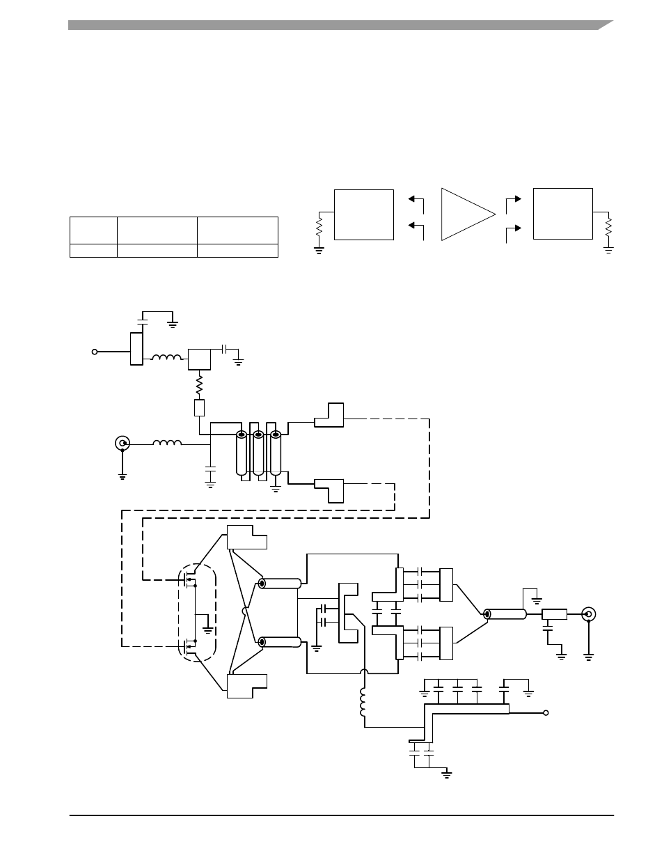
CIRCUIT DESCRIPTION
The input circuit uses a 9/1 balun transformer with a
prematch done by a series inductor and a shunt capacitor.
The shunt capacitor is optional but is useful to center the
input return loss (IRL). The input circuit return loss is always
better than 10.5 dB, equivalent to a worst case VSWR of 1.8.
The output circuit consists of a 4/1 transformer using two
4.7″ lengths of 10 Ω coaxial cable. It is also recommended
that three DC blocks in parallel be used in order to lower the
total equivalent series resistance (ESR) which is critical at
this high power.
The output balun is made from a 6.7″ length of “Sucoform
250” 50 Ω coaxial cable, and acts as a Pi match with
2 x 15 pF at the input and 5.6 pF at the output.
FIXTURE IMPEDANCE
V
DD
= 50 Vdc, I
DQ
= 200 mA, P
out
= 1100 W CW
f
MHz
Z
in
Ω
Z
out
Ω
144
1.6 + j5.0
3.9 + j1.5
Figure 2. Series Equivalent Source and Load Impedance
Figure 3. 2 Meter Amateur Reference Design Schematic Diagram
C7
C8
C9
C10
C11
C12
RF
OUTPUT
C4
COAX1
COAX2
COAX3
C5
C6
C19 C20
C17
C16
C15
C18
V
DD
C13
C14
L2
B1
C1
V
GS
C3
R1
C2
L1
RF
INPUT
T1
Z source
Z load
Input
Matching
Network
Device
Under
Test
Output
Matching
Network
--
--
+
+