Communication Concepts 2M 1KW Amateur Application Note User Manual
Page 6
6
RF Reference Design Data
Freescale Semiconductor
MRFE6VP61K25H MRFE6VP61K25HS 2 Meter Amateur
IMD MEASUREMENT
IMD measurement was done using two signal generator
with a tone spacing of 1 kHz. Quiescent current was set for
2.5 A under 50 volts with no RF signal at input. 2.5 A was
choosen as a good compromise between gain, linearity and
efficiency.
In order to get optimal linearity, a thermal compensation
circuit was used that tracks the quiescent current of the
board over the temperature range (not shown on picture).
Refer to AN1643 RF LDMOS Power Modules for GSM Base
Station Application: Optimum Biasing Circuit
(1)
or the VHF
Broadcast Reference Design for more information.
(2)
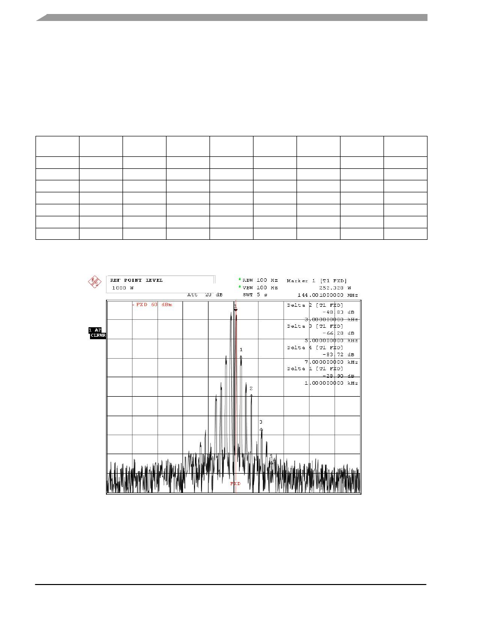
The two--tone IMD values are referenced to the peak
envelope power (PEP) and are spaced 1 kHz apart.
Table 5. Two--Tone IMD
P
out
(W) PEP
IM3--L
IM3--U
IM5--L
IM5--U
IM7--L
IM7--U
IM9--L
IM9--U
100.0
--42.2
--42.2
--61.3
--64.1
--72.5
--74.4
--85.1
--85.1
199.5
--42.0
--42.3
--57.8
--59.6
--69.9
--70.6
--75.2
--78.0
399.8
--44.8
--44.0
--50.8
--51.7
--66.6
--68.2
--73.3
--72.1
599.3
--41.7
--41.5
--45.1
--45.5
--68.1
--71.7
--68.1
--68.9
797.1
--33.7
--33.7
--42.4
--42.2
--56.5
--57.3
--68.5
--65.9
899.8
--30.8
--30.9
--42.0
--41.8
--51.9
--52.4
--68.0
--69.5
997.8
--28.7
--28.6
--42.7
--42.3
--48.6
--48.7
--73.7
--73.4
at e:
3. NOV .20 10
1 4: 48:
D
19
Figure 6. 1000 W PEP Two--Tone Spectrum