Computer hardware installation on vertical bracket, Cable management – CHIEF KSA1022 User Manual
Page 13
Installation Instructions
KSA-1022
13
Computer Hardware Installation on Vertical
Bracket
WARNING:
Exceeding the weight capacity can result in
serious personal injury or damage to equipment! It is the
installer’s responsibility to make sure the weight of each
component attached to the KSA-1022 wall track accessory
does not exceed 25 lbs (11.3 kg) or the specific weight limit
for the attached mounting device. Additionally, there is a limit
on how many components may be mounted on each bracket
depending on the mounting method. Refer to the table below
for details.
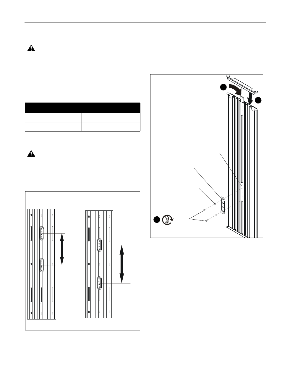
WARNING:
For vertical mounting on wood or steel studs, a
minimum distance of 8" must exist between mounted
devices. For vertical mounting on drywall, a minimum
distance of 16" must exist between mounted devices. (See
Figure 22)
Figure 22
1.
Remove side cover to slide locking plate brackets (B) into
wall track accessory (A) at the desired mounting location.
(See Figure 23)
NOTE:
Locking plate brackets must be inserted into center
channel on wall track accessory.
2.
Reinstall side cover to wall track accessory after all locking
plate brackets have been inserted. (See Figure 23)
Figure 23
3.
Use hex key (J) to install #10 button head cap screws (E)
through #10 washers (H) and wall plate (not included) into
center holes of locking plate brackets (B). (See Figure 23)
4.
Refer to corresponding installation manual to complete
installation of specific computer hardware.
NOTE:
Wall brackets must be secured by installing screws
through the top and bottom holes of the bracket. (See
Figure 23)
Cable Management
NOTE:
Complete installation of computer hardware prior to
enclosing the cable within the wall track accessory.
1.
Tuck cable inside cable management flap. (See Figure 22)
2.
Remove side cover to wall track accessory.
3.
Pull cable through cable management flap until cable outlet
plug extends outside the wall track accessory. (See Figure
22)
Two Mount Maximum
Three Mount Maximum
Horizontal, dual stud mounting
Horizontal, triple stud mounting
Vertical, drywall mounting
Vertical, single stud mounting
Wood or Steel Studs
Drywall
8"
minimum
16"
min
((B)
(E) x 2
3
(H) x 2
wall bracket
1
2
(B)