6 unbalance optimisation, 7 automatic minimization of static unbalance, 8 eccentricity measurement (option) – CEMB USA C72_2SE EVO (B) User Manual
Page 14: English
14
s
sx
x
g
g
g
g
d
dx
x
5
50
0°°
s
sx
x
g
g
g
g
d
dx
x
4
4 g
g
3
3 g
g
1
1 g
g
6
6 g
g
s
sx
x
g
g
g
g
d
dx
x
s
sx
x
g
g
g
g
d
dx
x
s
sx
x
g
g
g
g
d
dx
x
A
B
Use and maintenance manual Rev. 12-2009
ENGLISH
5.6 UNBALANCE
OPTIMISATION
This operation is performed to reduce the static unba-
lance of the wheel.
It is suitable for static unbalance values in excess of 30
grams.
I
a. f no unbalance was measured before, START appears
on the display. Press this button to proceed.
Mak
b.
e a reference mark on the flange and the rim (using
a piece of chalk, for example).
With the aid of a tyre remover, turn the tyre on the rim
by 180°.
Refi t the wheel in such a way that the reference marks
on the rim and the fl ange coincide.
Press START to begin reading.
RH displ
c.
ay: percentage reduction value
LH display: actual static unbalance value which can be
reduced by rotation
Ma
d.
rk the two positions of the rim and tyre, and turn the
tyre on the rim until the positions coincide to achieve
the optimisation shown on the display
To cancel optimisation at any time, press
.
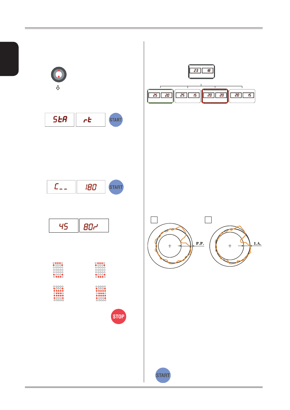
5.7 AUTOMATIC MINIMIZATION OF STATIC
UNBALANCE
This program is designed to improve the quality of balancing
without any mental effort or loss of time by the operator. In
fact by using the normal commercially available weights, with
pitch of 5 in every 5 g, and by applying the two counterweights
which a conventional wheel balancer rounds to the nearest
value, there could be a residual static unbalance of up to 4
g. The damage of such approximation is emphasized by the
fact that static unbalance is cause of most of disturbances
on the vehicle. This new function, resident in the machine,
automatically indicates the optimum entity of the weights
to be applied by approximating them in an “intelligent” way
according to their position in order to minimize residual static
unbalance.
5.8
ECCENTRICITY MEASUREMENT
(OPTION)
The much enlarged fi gures show the outer tyre surface
and axis of wheel rotation.
Fig. A - shows measurement of the total Peak-to-Peak
eccentricity defi ned as maximum radial deviation of the tyre
surface.
Fig. B - shows measurement of the eccentricity of the 1st
harmonic, i.e. the eccentricity of that circle which “recopies”
the tyre shape, by averaging the local deviations of the tyre
from the round shape.
Obviously the P.P. measurement is normally greater than that
of the 1st harmonic. Tyre manufacturers normally supply two
different tolerances for the two eccentricities.
The radial eccentricity measurements is automatically carried
out after the unbalance measurement without having to go into
particular procedures. Remember to position the sonar sensor
in front of the surface to be measured before pressing
the
button.
Initial unbalance
Phase shift
Possible approximations
static residue
static residue
static residue
static residue
With traditional wheel
balancer
Choice with minimum static
unbalance
Use of the wheel balancer
RIM
POSITION
TYRE
POSITION