5use of the wheel balancer – CEMB USA C72_2SE EVO (B) User Manual
Page 11
11
a
b
b
Use and maintenance manual Rev. 12-2009
ENGLISH
5
Use of the wheel balancer
5.1
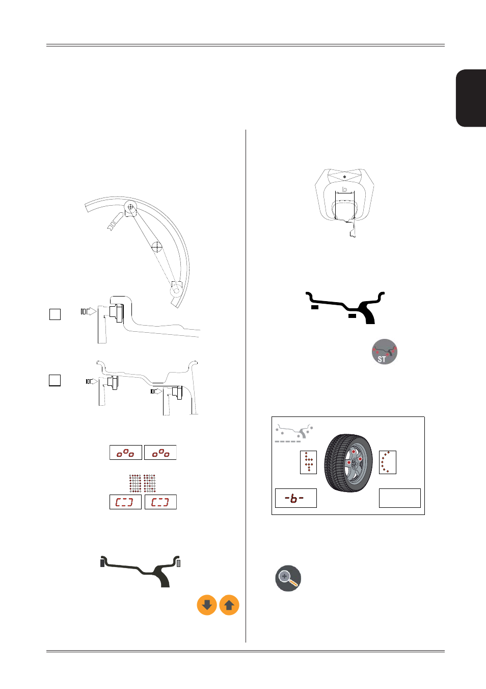
PRESETTING OF WHEEL DIMENSIONS
The balancing data is set by means of an “intelligent” au-
tomatic gauge; confi rmation of the measurement and the
position appear on the display. The round part of the gauge
must rest on the rim where the weight will be positioned.
While the gauge is moving the following appears:
when the measurement has been stored:
a) standard weights: when only one measurement is
made, the machine interprets the presence of a rim with
clip-on weight correction
The width value (b) must be set with the
buttons .
Use of the wheel balancer
The correct measurement is that which can be measured
with the compass gauge provided.
b) adhesive weights: make two successive measurements
on two correction planes inside the rim.
The balancing machine automatically interprets that the
correction will be made with adhesive weights and the
following appears:
For a different combination of the type or position of the
weights on the rim, use the button
.
AUTOMATIC WIDTH (OPTION)
At the end of automatic distance and diameter measure-
ment, if the LA sonar is present, the machine prepares
for acquisition of this value:
The LT script on the LH matrix display indicates that LIGHT
TRUCK wheel measurement is set (large dimension wheels
such as off-road, trucks or wheels which protrude signifi cantly
from the rim).
This function can be enabled/disenabled by pressing push
button
. Slowly close the wheel guard until a
“beep” is heard. If “AUTOMATIC START” is enabled when
the guard is closed, the balancing machine performs a
cycle to measure the imbalance, otherwise the width value
just acquired is shown.