1 modifying set dimensions, 2 measurement result – CEMB USA C72_2SE EVO (B) User Manual
Page 12
12
FI
FE
Use and maintenance manual Rev. 12-2009
ENGLISH
Press the button
to perform a spin.
5.1.1 Modifying set dimensions
If the wheel dimensions have been entered incorrectly,
the parameters can be modified without repeating the
balancing spin by pressing for 2 seconds :
access parameter modifi cation
→
(select
to modify: (a) distance, (b) width, (d)
diameter
In the case of standard weights:
(a)distance,(b)width,(d)diameter
In the case of adhesive weights:
(a1) inside distance,(a2) outside distance,(d1) inside
diameter,(d2) outside diameter
press
to select (a) (b) or (d)
→
to recalculate the unbalance
or:
pull out the gauge to repeat the measurement
→
to obtain the new measurement.
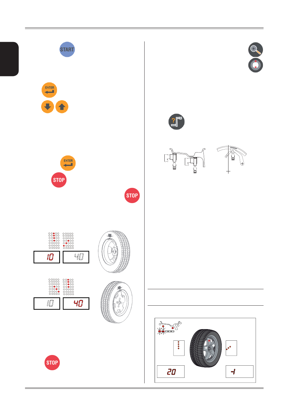
5.2 MEASUREMENT
RESULT
Move the wheel manually until all the LED’s correspond-
ing to the side light up. The display shows the measured
unbalance. If the wheel clamp option is enabled (see
MENU
), the wheel is automatically clamped in the correc-
tion position.
Pressing
the chuck can be locked/released in any
position to facilitate mounting the wheel (see
MENU
).
For unbalance within tolerance 0 (zero); using
values within tolerance can be viewed.
If the static unbalance is greater than 30 g, the LED
fl ashes to suggest an unbalance optimisation operation
(see
UNBALANCE OPTIMISATION
).
5.3 EXACT POSITIONING OF THE ADHESIVE
WEIGHT BY MEANS OF THE GAUGE WITH
CLIPS
P
▪
ress
if using the correction method with
adhesive weights on the inside of the rim
Fit the correction weight in the specific gauge seat with
▪
the adhesive part facing upwards
Bring the wheel into correct angular position for the
▪
plane to be corrected
If the wheel clamp option is enabled (see
▪
MENU
),the wheel
is automatically clamped in the correction position.
Pull out the gauge up to the distance set
▪
(see
WHEEL
DIMENSIONS PRESETTING
b/c)
If the buzzer is enabled (see
▪
MENU
), the attainment
of the weight application distance is accompanied by
a beep.
Using the special weight pusher, rotate the gauge until
▪
the correction weight adheres to the rim.
If gauge locking is enabled (see
▪
MENU
), the gauge is
automatically locked when the weight application distance
is reached. To release the gauge, lower it to below 10”
diameter
the fact that the weight application position is no longer
▪
vertical is automatically compensated.
INDICATION
The approach of the weights to the correction positions
is indicated by the LEDs number 19
► Inside
Use of the wheel balancer