2 aluminium rims – CEMB USA ER100 (A) User Manual
Page 23
23
Use and Maintenance Manual Rev. 11-2010
ENGLISH
Displays the information screen
Selects unbalance display in g/oz
Displays the approximate values
Enables/disables spindle rotation
Splits the unbalance
Displays the second set of buttons
Lift reset with wheel stopped / STOP during spin
Use of the wheel balancing machine
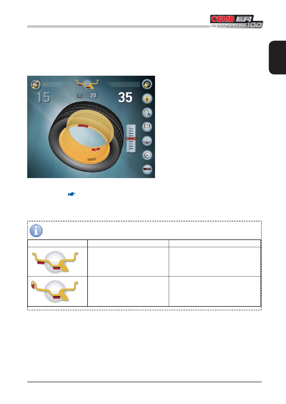
6.7.2 Aluminium rims
After the spin, the laser indicates the outside correction point; once you have applied the weight, press the “laser
positioning” button (
TECHNICAL DESCRIPTION
) positioned on the weight tray of the wheel balancing machine to
move the laser so that it indicates the inside correction position.
The inside unbalance values indicated by the laser are graphically displayed in white.
WEIGHT APPLICATION POSITION
Correction type
Inside
Outside
Adhesive weight at the point indicated
by the internal laser
Adhesive weight at the point indicated by the
internal laser
Clip-on weight at 12 o’clock
Adhesive weight at the point indicated by the
internal laser