4 unbalance measurement (first set of buttons), 1 spindle rotation lock/release, English – CEMB USA ER100 (A) User Manual
Page 19
19
Use and Maintenance Manual Rev. 11-2010
ENGLISH
Use of the wheel balancing machine
Displays the information screen
Selects unbalance display in g/oz
Displays the threshold
Enables/disables wheel rotation
Splits the unbalance
Displays the second set of buttons
Lift reset with wheel stopped / STOP during spin
6.4
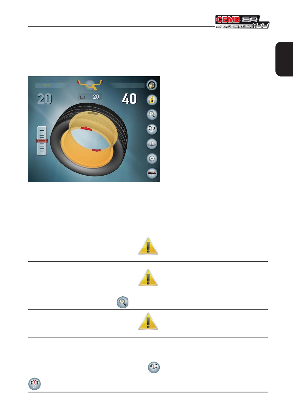
UNBALANCE MEASUREMENT (first set of buttons)
To perform an unbalance measurement spin, close the guard.
After performing a balancing spin, the following are displayed:
The unbalance values.
1.
White: wheel locked in correction position / Internal scanning laser positioned on the side.
▪
Light blue: position not reached / Internal scanning laser not positioned.
▪
The red weights that indicate the unbalance position.
2.
The weight shadows that indicate where the correction weight should be applied: at the top at 12 o’clock or at the
3.
point indicated by the internal laser.
I
F
THE
“
WHEEL
IN
POSITION
”
SOUND
IS
ENABLED
,
A
SOUND
WILL
BE
EMITTED
WHEN
THE
CORRECTION
POSITION
HAS
BEEN
REACHED
.
I
F
THE
UNBALANCE
IS
LESS
THAN
THE
THRESHOLD
VALUE
SET
, OK
IS
DISPLAYED
INSTEAD
OF
THE
UNBALANCE
VALUE
TO
INDICATE
THAT
THE
WHEEL
IS
WITHIN
TOLERANCE
ON
THAT
SIDE
.
P
RESSING
THE
BUTTON
YOU
CAN
IN
ANY
CASE
VIEW
THE
RESIDUAL
UNBALANCE
.
T
O
RESUME
WITH
THE
DIMENSIONS
OF
THE
WHEEL
MOUNTED
,
OPEN
AND
CLOSE
THE
SPINDLE
.
6.4.1 Spindle rotation lock/release
The wheel balancing machine automatically locks spindle rotation if there is an unbalance in the correction position
on one of the sides. To release rotation, press the button
or turn the wheel with force.
If rotation is released and you need to lock it (for example, to facilitate mounting large wheels), press the button
.