CEMB USA C218 (A) User Manual
Page 5
I 0568 - 5
A
B
3
GB
3 - COMMISSIONING
3.1 - Electrical connection
WARNING:
The electrical connection must be made by specialized personnel. Connection to
the single phase mains must be made between phase and neutral, and never, under
any circumstances, between phase and earth (ground). Effi cient earthing
(grounding) is essential for correct machine operation. The manufacturer declines
all responsibility and warranty in the event of incorrect connection.
Before connecting the machine to the mains through relative cable, check that the mains voltage matches the one
shown on the nameplate at the back of the balancing machine. Rating of the electrical connection should be on the
basis of the machine electrical power consumption (see nameplate).
▪ The machine mains supply cable should be fi tted with a plug conforming to current regulations.
▪ It is recommended to provide the machine with its own electrical connection through a slow acting safety switch
rated at 4 A (230 V) or 10 A (115 V).
▪ When connection is made directly to the main control panel without using any plug, it is advisable to padlock the
main switch of the balancing machine in order to limit its use to authorized personnel only.
3.2 - Pneumatic connection
The machine must be connected to the compressed air supply and must not be used if the pressure is below 5 kg/
cm2 (5 bar; 72 PSI; 0.5 MPa). The maximum input pressure is limited to 10 kg/cm2 (~10 Bar; ~145 PSI; ~1 MPa).
The connection is made on the rear of the machine. The air circuit is designed to ensure signifi cant “elasticity” of
movement for the lift whatever the position of its travel; this means that the position of the wheel can be adjusted with
minimal manual effort. The spinning and braking device is calibrated at the factory and cannot be modifi ed.
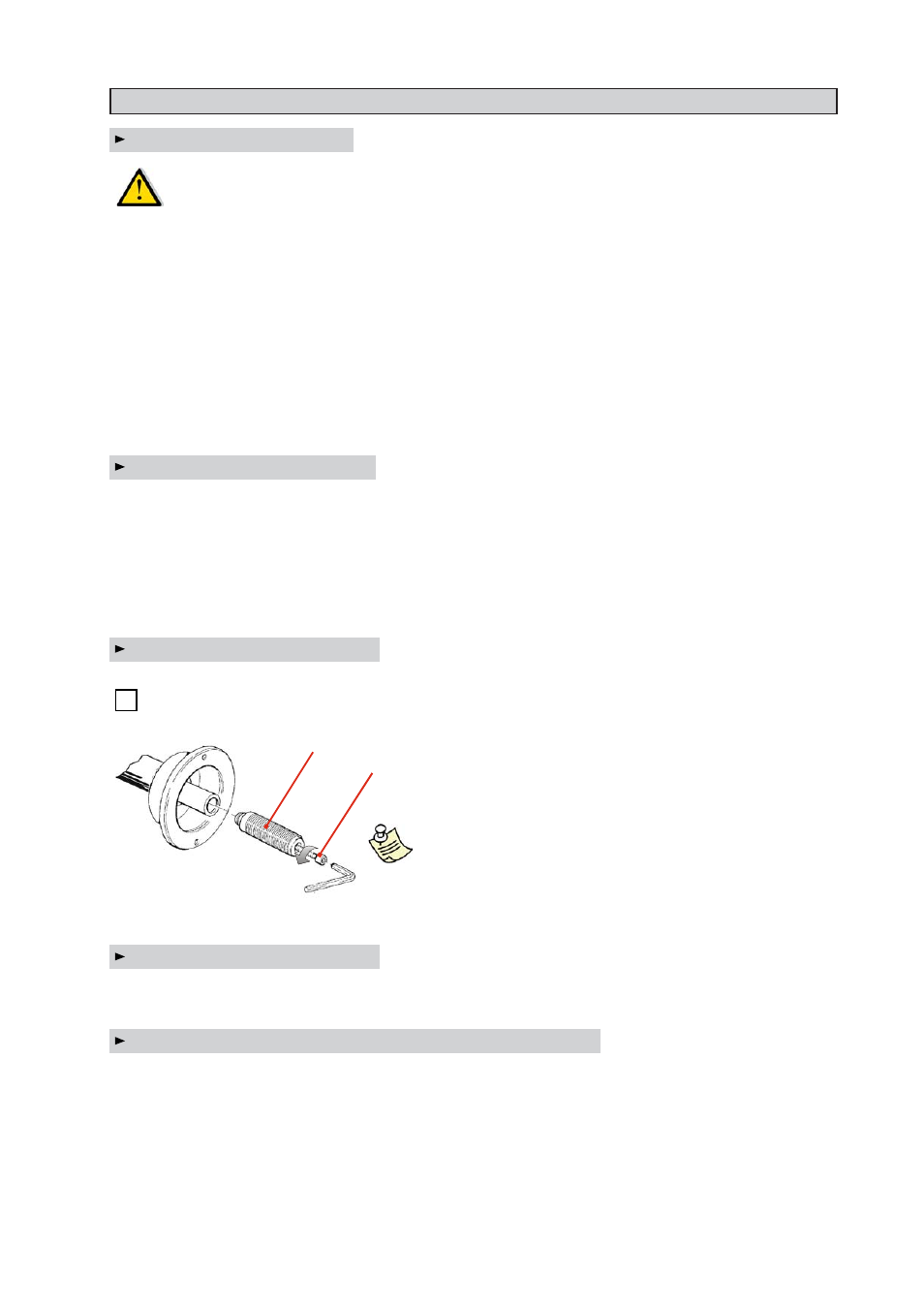
3.3 - Adapter mounting
The wheel balancer is supplied complete with cone type adapter
for fastening wheels with central bore.
Other optional adapters can be mounted:
a) Remove threaded end piece A after backing
off screw B.
b) Mount the new adapter (see enclosed brochures)
N.B. : Carefully clean the coupling surfaces before
performing any operation.
3.4 - Wheel mounting
The wheels should be fastened with one of the numerous adapters manufactured by CEMB (see enclosed
brochures). N.B.: Incorrect centering inevitably causes unbalance.
3.5 - Guard mounting and adjustment (option)
a) Fasten the components to the base as illustrated in specifi c exploded view.
b)The positions of these guards can be adjusted using the special screws accessed from inside the main support.
c) Check that the microswitch is held down when the guard is closed.
d) Adjust the angular position of microswitch control.