2 presetting of tolerance on the, 4 value of unbalance corresponding to eccentricity, 11 wheel eccentricity measurements – CEMB USA ER85 (A) User Manual
Page 17: 2 presetting of tolerance on the machine
17
A
B
Use and maintenance manual Rev. 09-2013
ENGLISH
5.10.2 Presetting of tolerance on the
machine
There is no general rule concerning acceptability of an eccen-
tricity value . As a first approximation we consider it correct
to use a threshold of 1 to 1.5 mm. The E/ECE/324 standard
prescribes 1.5 mm as max. eccentricity of a rebuilt tyre.
5.10.3 Value of static unbalance, correlated
with eccentricity
Clear indication is given in the Measurement screen of both
the value and position of the static unbalance as well as the
eccentricity. In fact, it is interesting to check the correlations
of the two values, above all of the two positions. When the
two positions have a similar angle (± 30° one from the other),
there is a clear sign that an eccentricity is present which
can be compensated by matching.
5.10.4 Value of unbalance corresponding to
eccentricity
For user’s reference, the centrifugal force is calculated corre-
sponding to a certain speed, compared to the force generated
by the eccentricity present on the tyre (calculated with an
approximate average elastic constant).
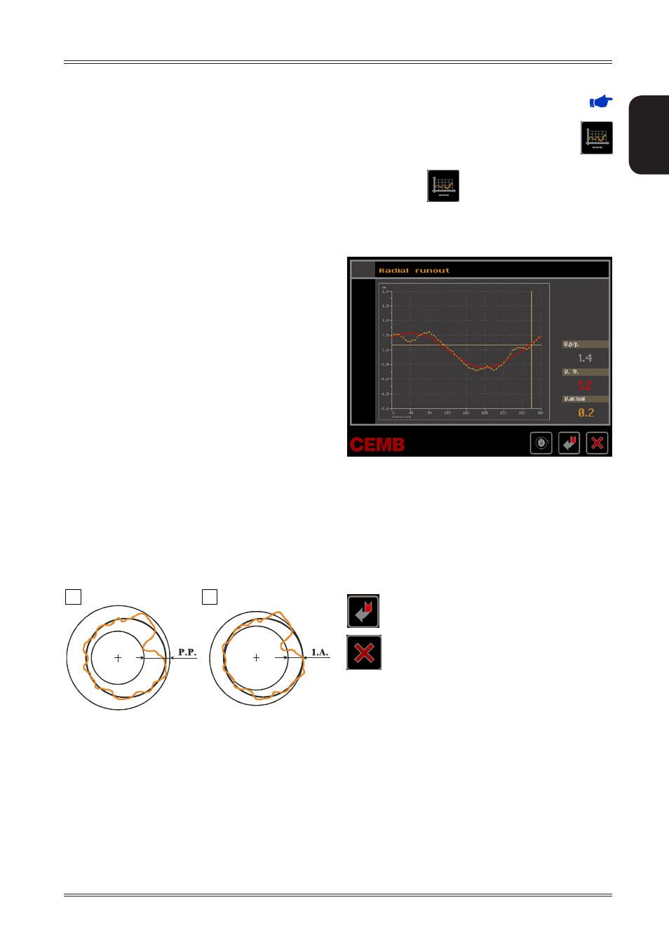
5.11 WHEEL ECCENTRICITY
MEASUREMENTS
The external radial eccentricity measurement is taken auto-
matically at the end of the unbalance measurement without
having to perform specific procedures; remember to position
the sonar sensors in front of the surface to be measured
before performing a spin.
The much enlarged figures show the outer tyre surface and
axis of wheel rotation.
Fig. A - shows measurement of the total Peak-to-Peak eccen-
tricity defined as maximum radial deviation of the tyre surface.
Fig. B - shows measurement of the eccentricity of the 1st
harmonic, i.e. the eccentricity of that circle which “recopies”
the tyre shape, by averaging the local deviations of the tyre
from the round shape.
Obviously the P.P. measurement is normally greater than that
of the 1st harmonic. Tyre manufacturers normally supply two
different tolerances for the two eccentricities.
The maximum limit of the first harmonic can be set (
FIRST HARMONIC LIMIT
). When this limit is exceeded,
the wheel balancer displays the red symbol above the
button to indicate an eccentricity condition that needs to be
corrected. Press
on the unbalance measurement
screen to display the eccentricity measurement graph.:
Use of the wheel balancer
GRAPH 1 (yellow): shows the real peak-to-peak eccentricity.
GRAPH 2 (red): shows the first harmonic eccentricity.
An almost straight line graph indicates a wheel in perfect
condition.
When the wheel is moved the cursor on the graph indi-
cates the current value with the phase referred to the
measurement sensor.
The following buttons are enabled:
to
start an eccentricity optimization (
ECCENTRI-
CITY OPTIMIZATION
)
to return to the unbalance measurement frame.