3 user control, 4 result of measurement, 5 wheel locking – CEMB USA ER85 (A) User Manual
Page 13
13
Use and maintenance manual Rev. 09-2013
ENGLISH
5.3 USER CONTROL
Allows storing the dimensions of three types of wheels.
In this way three users can work on three different vehi-
cles at the same time using the same wheel balancer.
The system keeps three programs in memory, each with
different dimensions set.
1. Press one of the three buttons to select the user
(1, 2, 3).
2. Enter the dimensions.
3. Lower the guard to balance the wheels as normal
and automatically store the program for the user
currently selected.
When selecting the user
, the relative pro-
gram (1, 2 or 3) is called for subsequent wheel balancing
operations without having to enter the dimensions again.
INdIcATIoN
Remember to set correctly the dimensions in the manner
already decribed in the paragraph “PRESETTING OF
WHEEL DIMENSIONS”.
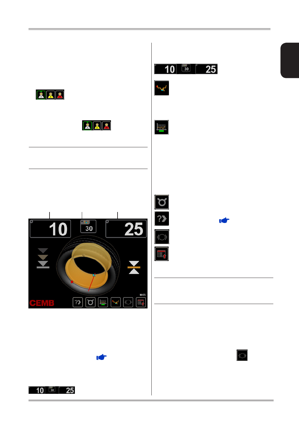
5.4 RESULT OF MEASUREMENT
Lower the guard to make a measurement spin.
Close the guard to perform a
measurement
spin.
If laser option = OFF : after positioning and locking the wheel,
apply the weight vertically at the top.
If laser option = ON : apply the clip-on weights at 12 o’clock.
If using adhesive weights, when the correction position is
reached, the laser turns on indicating the point where to apply
the adhesive counterweight.
When the beep signal is enabled (
ACOUSTIC SIGNAL
),
reaching of the correction position is accompanied by a “beep”.
If the out-of-balance is less than the chosen threshold value,
“0K” appears instead of the out-of-balance value to indicate,
on that particular side, that the wheel is in tolerance;
press
on the unbalance indicators to display
Use of the wheel balancer
the residual value to a precision of 0.5 g (0.1 oz.).
The following buttons are enabled:
display of residual out-of-
balance.
selection of correction mode (STATIC/DUAL
SURFACE). When the mode is changed, the
unbalance values are recalculated automati
cally on the basis of the previous spin.
Simultaneous display of the dynamic+static
unbalance can be enabled through the special
function in Setup (see par.
STATIC ALWAYS
ENABLED
).
eccentricity measurement graph
N.B : 1. The symbol above the key is displayed
in yellow if the first harmonic eccentricity
exceeds the limit set in the setup parameters
(
FIRST HARMONIC LIMIT
).
2. When this push button is held down for more
than 1.5 seconds, eccentricity measurement is tem-
porarily disenabled (enabled in
SETUP
). To re-ena-
ble eccentricity measurement, press push button
[4] again for more than 1.5 seconds. Every time the
machine is switched on, the status of eccentricity
measurement reflects the settings in
SETUP
.
unbalance split function enable
enable indication of the longitudinal position of
the out-of-balance (
INDICATION OF
EXACT CORRECTION WEIGHT POSITION
)
wheel lock/unlock
selection of special functions
Close the guard to perform a balancing spin.
INdIcATIoN
If the machine remains on this screen without being
used for more than the time preset in the Setup
parameters, the screen automatically returns to the
screen-save.
5.5 WHEEL LOCKING
The wheel is automatically locked when reaching the correct
angular position for weight application on the inside and
outside, turning it slowly by hand. To unlock the wheel, turn
it hard to move it from the correct correction position.
If the unbalance is within tolerance, the wheel is not
automatically locked. By pressing the
button it is
possible to lock/release the spindle in any position to
facilitate the wheel assembly.
Inside unbalance
indicator
Outside unbalance
indicator
Static unbalance
indicator