7 “split” control (hidden weight) – CEMB USA ER85 (A) User Manual
Page 14
14
FI
FE
Use and maintenance manual Rev. 09-2013
ENGLISH
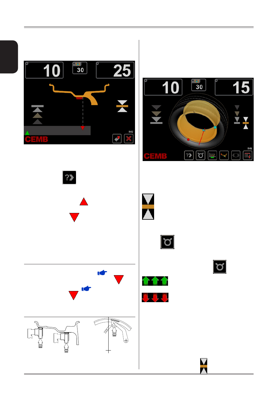
5.6 EXACT POSITIONING OF THE ADHESIVE
WEIGHT BY MEANS OF THE GAUGE
WITH CLIPS
The position repeater screen can be accessed in 2 dif-
ferent ways:
▪ Pull out the gauge after placing the wheel in the correc
tion position on one of the two sides
▪ Press the button
at any time
Always pull out the gauge to position A as shown in figure
page 12
▪ A mobile coloured arrow [
] indicates the approach
of the weight towards the correction position.
▪ When a fixed arrow [
] is reached, rotate the wheel
to correction position (FI or FE) and apply the
counterweight by rotating the gauge tip towards the
outside, into the position where the pincer touches the
wheel (where appropriate use the weight pusher).
▪ The correction weight application position is automati
cally reset in relation to the position of the distance +
diameter gauge (pos. A).
INdIcATIoN
When the acoustic signal is enabled (
ACOUSTIC
SIGNAL), attainment of the fixed arrow status [
] is
accompanied by a “beep”.
If gauge locking is enabled (
GAUGE LOCKING),
when a fixed arrow [
] is reached,
the gauge is automatically locked to prevent shifts during
application of the correction weight. To release and bring
the gauge back to the rest position, lower it to below 10”
diameter.
Use of the wheel balancer
5.7 “SPLIT” CONTROL (HIDDEN WEIGHT)
SPLIT is only possible in the event of static unbalance
or ALUS external side and is used to hide any adhesive
weights correcting unbalance behind the rim spokes.
If laser option = OFF
To split the unbalance detected in two different positions,
proceed as follows :
1. Position static unbalance or ALUS external side in the
correction position :
2. Select a spoke close to the 12 o’clock postion to be cor
rected, more it into the 12 o’clock position and press
button
3. Turn the wheel in the rotation direction indicated on the
unbalance display, brining the second spoke to the 12
o’clock position and press button
Turn the wheel in direction of rotation.
Turn the wheel in reverse direction of
rotation.
4. At this point, two indications appear on screen for posi-
tioning of the unbalance correction spokes.
5. Position the spokes indicated on screen in the 12 o’clock
position and correct with the value displayed.
If laser option = ON
To split the unbalance measured in two different positions,
operate as follows:
1. Position the static unbalance or outside ALUS in the
in the correction position: