8 correction mode, 9 automatic minimization of static unbalance, English – CEMB USA ER85 (A) User Manual
Page 15
15
sx
g
g
dx
50°
sx
g
g
dx
4 g
3 g
1 g
6 g
sx
g
g
dx
sx
g
g
dx
sx
g
g
dx
Use and maintenance manual Rev. 09-2013
ENGLISH
2. Press
and hold down until the laser points
to
the spoke where you want to correct
3. Release the
button
4. Turn the wheel in the unbalance rotation direction
indicated on the display until the second spoke is in
the position indicated by the laser and press the
button
5. At this point, two indications appear on screen for
positioning of the unbalance correction spokes
6. Move the spokes indicated to the correction position
and correct the value displayed
Any error in this procedure is clearly shown on screen.
Always follow the information provided by the wheel to
optimise correction.
5.8 CORRECTION MODE
After having performed automatic measurement of the inner
side, it is possible to place the correction weights as required
by pressing
push buttons
INdIcATIoN
In the event of automatic measurement of both sides, if
the difference between the inner and outer diameters is
greater than or equal to 2”, the system sets the inner side
spring weight.
To modify this presetting, press the
button.
To display static unbalance, press the
button on the measurement screen (for ALUS static,
the inner side diameter is always considered).
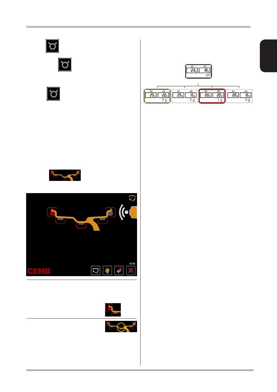
5.9
AUTOMATIC MINIMIZATION OF STATIC
UNBALANCE
This program is designed to improve the quality of balancing
without any mental effort or loss of time by the operator. In
fact by using the normal commercially available weights, with
pitch of 5 in every 5 g, and by applying the two counterweights
which a conventional wheel balancer rounds to the nearest
value, there could be a residual static unbalance of up to 4
g. The damage of such approximation is emphasized by the
fact that static unbalance is cause of most of disturbances
on the vehicle. This new function, resident in the machine,
automatically indicates the optimum entity of the weights
to be applied by approximating them in an “intelligent” way
according to their position in order to minimize residual static
unbalance.
Use of the wheel balancer
Initial unbalance
Phase shift
Possible approximations
static residue
static residue
static residue
static residue
With traditional wheel
balancer
Choice with minimum static
unbalance