3 setting up your at-8, 1 frame assembly – Castle AT-8 Operator Manual User Manual
Page 9
CASTLE, INC
AT‐8 OWNERS MANUAL V2.1
Page 9 of 30
3 Setting Up Your AT-8
Your Castle AT-8 Assembly Table is shipped knocked-down, with the legs bolted to a pallet and
the frame and top inside.
3.1 Frame Assembly
1. Remove the clamp arm from the pallet by cutting the two zip ties.
2. Unbolt the legs on the narrow side of the pallet and open them to an almost parallel posi-
tion.
3. Remove the packing envelope. In the envelope you will find the Operator Manual,
Warranty Card (which must be returned to Castle in order to activate your warranty)
and a Bolt Packs.
4. Remove the Fence/ Bracket packs. One pack located in the center of the table has
the Side and Bottom Fences. The other packs contain the Joining Plates and Leg
Supports.
NOTE: Parts are contained in the spacer package. Do not discard
5. Lift the 2 table tops out and set them aside for later use. Set a few 4 x 4’s on the
floor to prepare for the next step.
6. Unbolt the legs completely.
7. Place the frames face
down on the 4 x 4’s so that
the iron angle is facing up.
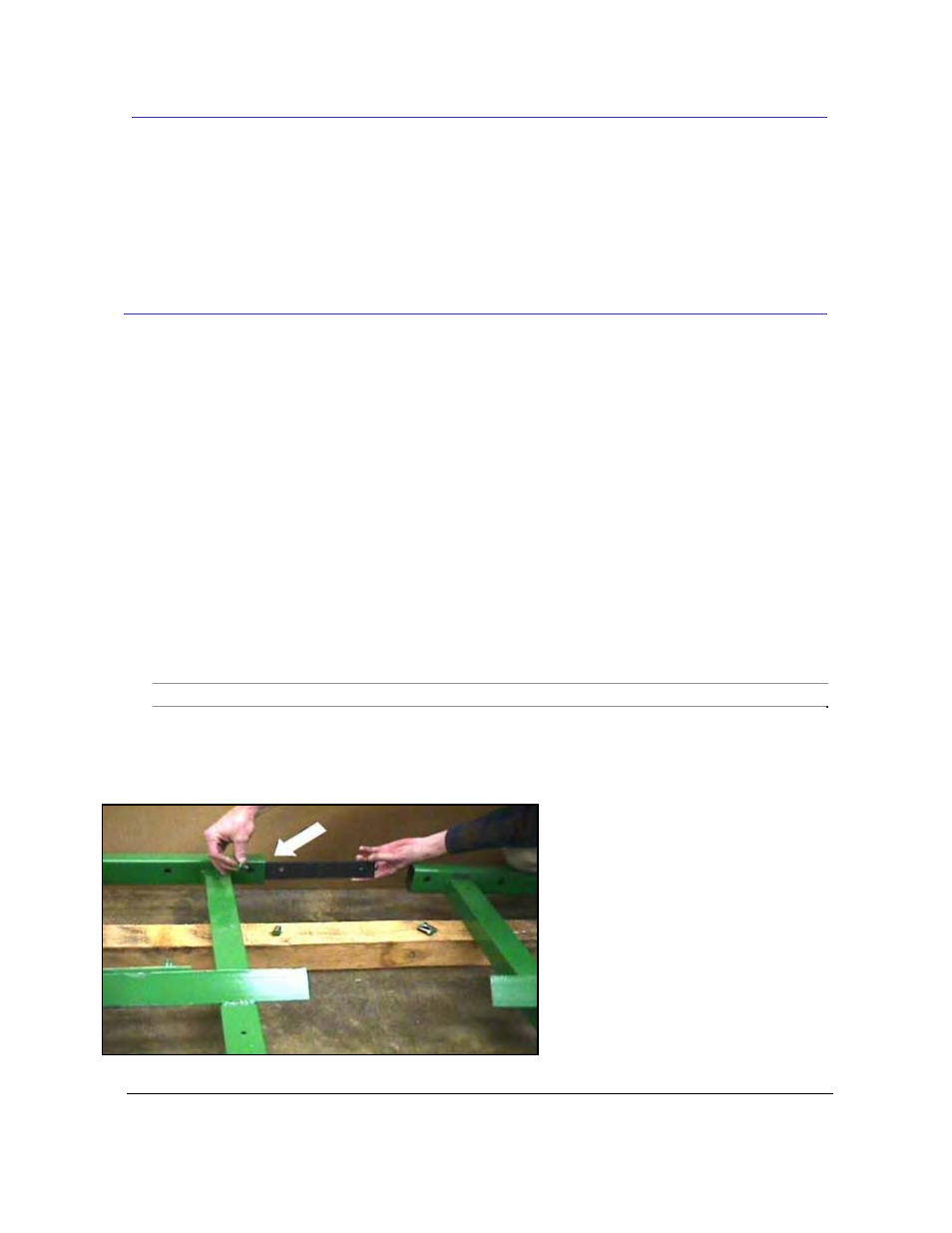
8. Position top joining plate
[G08513]
inside tube.