4 arm installation – Castle AT-8 Operator Manual User Manual
Page 15
CASTLE, INC
AT‐8 OWNERS MANUAL V2.1
Page 15 of 30
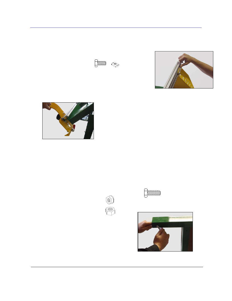
3.4 Arm Installation
1. Attach the arm bracket to the aluminum beam using the 5/16-18x5/8 HHCS bolts
[F51638]
and 5/16-18 T-nuts
[F51698]
supplied.
2. Position the clamp arm onto the frame from the right side.
3. The length of the arm may need to be adjusted at the upper
arm bracket.
4. Square the arm vertically by loosening 3 of the 4
bolts and drawing the arm parallel with the left
fence.
5. Slide the top bracket to achieve proper lower bearing adjustment.
6. Install the stop bolts through the holes in the back side of the top beam. The stop bolts
are necessary to keep the arm from sliding off the beam.
7. Stop Bolt Pack Includes:
a. (2) ¼ x 5/8 Hex Head Cap Screw
[F14585]
b. (2) ¼ Kep Nut
[F01422]
c. (2) ¼ Hex Nut
[F01423]