C.E. Niehoff & Co. N1506-1 Troubleshooting Guides User Manual
Page 2
Page 2
TG0018A
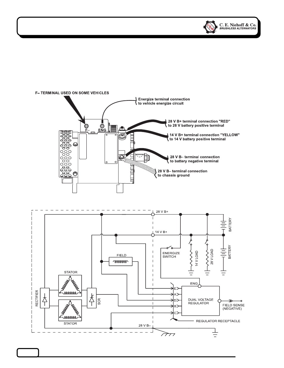
Section 1: Wiring Diagram
CEN N1506-1 Dual Voltage Alternator Description and Operation
N1506-1 100 A (28 /14 V) dual voltage alternator is internally rectified. All windings and current-transmitting
components are non-moving, so there are no brushes or slip rings to wear out. Energize switch (commonly an oil
pressure switch) activates regulator. Field coil is then energized. Upper voltage (28 V) is rectified with standard
diodes. Lower voltage (14V) circuit output current is controlled by SCRs in the drive end housing. Alternator
output current is self-limiting and will not exceed rated capacity of alternator.
N3030 regulator used with these units maintains alternator output voltage at regulated settings as vehicle electri-
cal loads are switched on and off.
Figure 2 — N1506-1 Alternator with Regulator
Figure 1 — N1506-1Alternator and N3030 Regulator Terminals
- 5-Pin Connector Extended Wiring Harness Installation (1 page)
- 6-Pin Connector Extended Wiring Harness Installation (1 page)
- 6-Pin Connector Extended Wiring Harness W_O Fuses Installation (1 page)
- 100: Regulator Upgrade (1 page)
- 200 & 300: Regulator Upgrade Installation (2 pages)
- 600/700/800 Service Tool (1 page)
- A1-102/A1-104 Installation (2 pages)
- A2-149/A2-155 Regulator Installation (1 page)
- A2-213/A2-214 Regulator Installation (1 page)
- A2-317 Regulator Installation (1 page)
- A2-325/A2-330/A2-336 Regulator Installation (1 page)
- A2-334/A2-335 Regulator Installation (1 page)
- A2-337 Regulator Installation (1 page)
- A2-341/A2-346 Regulator Installation (1 page)
- A2-344/A2-348/A2-350 Regulator Installation (1 page)
- A2-349 Regulator Installation (1 page)
- A3-201 Adjustable Pulley Installation (2 pages)
- A6-141 & A6-143 Fan Guard Screw Replacement (1 page)
- A7-113/114/115 Stator & Shell Assy Replacement (1 page)
- A8-128 Power Management System Installation (1 page)
- A8-219 Low Frequency EMC Filter Assembly Installation (1 page)
- A9-305 Med-to-High Frequency EMC Filter Assembly Installation (2 pages)
- A9-307 Alternator Voltage Filter Instructions (1 page)
- A9-309 Inline Harness Instructions (1 page)
- A9-462 Energize Interrupt Switch Installation (1 page)
- A9-4011 Temperature Sense Lead Instructions (1 page)
- A9-4036 TV/J1939 Harness Installation (1 page)
- A9-4039/A9-4050 Temperature-Voltage Sense Harness Instructions (1 page)
- A9-4056 Temperature Sensor Replacement (1 page)
- C102/C102-1 Installation (2 pages)
- C130/C131/C132 Inst/Parts Rep/TG Combo Guide (12 pages)
- C130 & C132 Alternator Installation (4 pages)
- C131 Alternator Installation (4 pages)
- C180etc and C181etc Installation (4 pages)
- C190 Series Installation (4 pages)
- C321 Alternator Installation (1 page)
- C326 Installation (1 page)
- C510 Alternator Installation (2 pages)
- C520 Alternator/A2-326 Regulator w/Extended Wiring Harnesses Installation (1 page)
- C524, C524-1, -3, -4 Alternator/A2-334 & A2-335 Regulator Installation (1 page)
- C527 Alternator Installation (1 page)
- C540 Alternator Installation (2 pages)
- C600 & C700: Stator Change Instructions (1 page)
- C600: A4-106 Tension Link Adjuster Instructions (2 pages)
- C612: A9-169 Upgrade Bearing Kit Instructions (1 page)