C.E. Niehoff & Co. N1326-1 Troubleshooting Guides User Manual
Page 4
Page 4
TG0059A
Section C: Advanced Troubleshooting
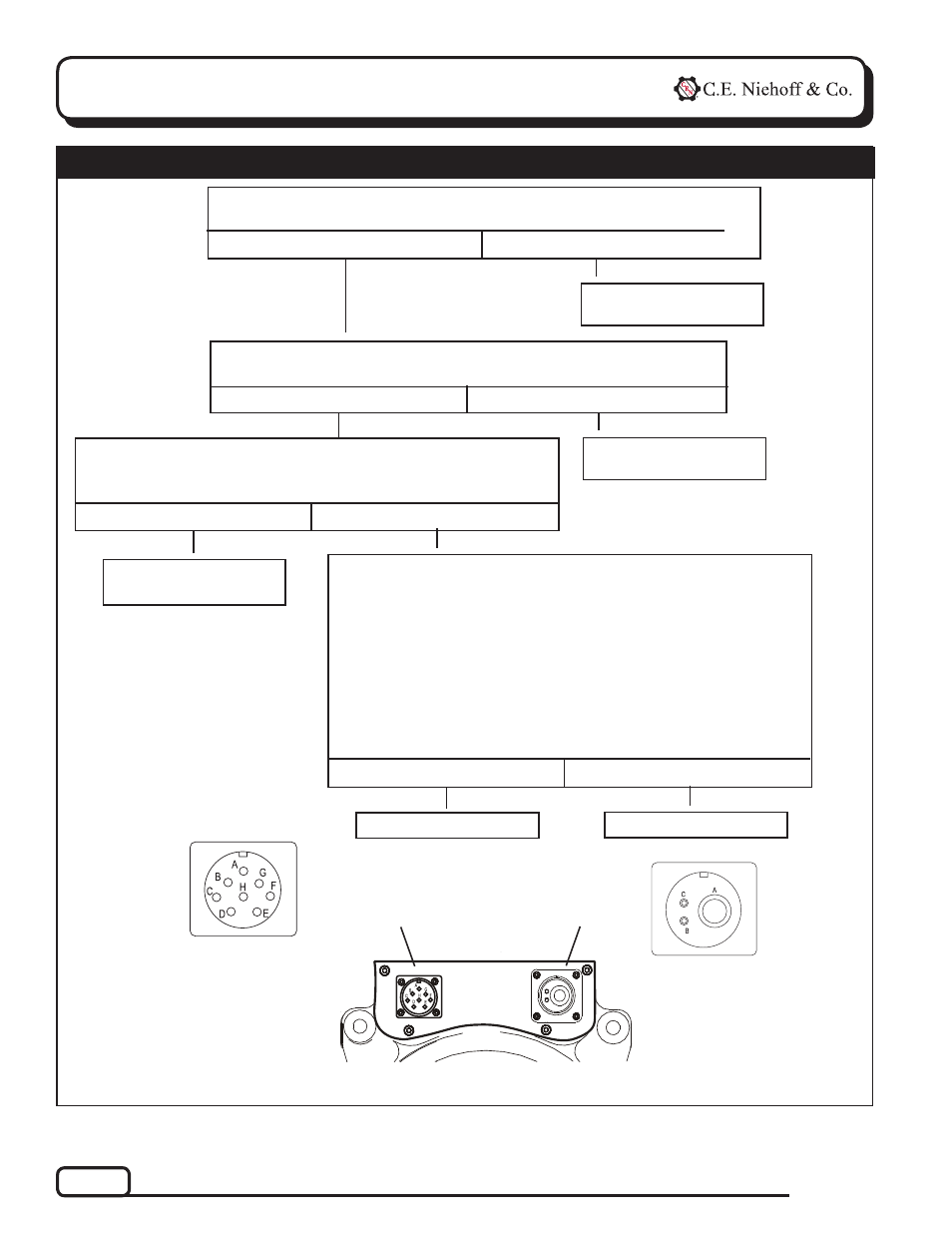
Chart 1 – No Output
If you have questions about your alternator or any of these test procedures, or if you need to locate a Factory Authorized Service Dealer, please contact us at:
C. E. Niehoff & Co.• 2021 Lee Street • Evanston, IL 60202 USA
TEL: (800) 643-4633 USA and Canada • TEL: (847) 866-6030 outside USA and Canada • FAX: (847) 492-1242
E-mail us at [email protected]
Figure 4 — N1326-1 Control Assembly
Ignition switch on, engine off: Check for battery voltage between B−
terminal on alternator and Pin A on output receptacle (back-probe pin).
Ignition switch off: Back-probing pins, momentarily (1 sec.) jumper
Pins A and B in output receptacle. Touch shaft with steel tool to
detect any magnetism. Is shaft magnetized?
Yes
No
Yes
No
Repair vehicle wiring to
output receptacle.
Check ignition switch
and vehicle wiring.
Disconnect regulator harness and output harness. Do the following
series of tests with DMM:
1. With meter set on ohms, check for continuity between pin A of
output receptacle and black lead to pin D of regulator receptacle.
2. With meter set on ohms, check field coil resistance across
pins A and D of regulator receptacle. Resistance should measure
less than 3 ohms.
3. With meter set on ohms, check for continuity between pin C of
regulator receptacle and B− terminal on alternator.
Did all three tests provide correct readings?
Yes
No
Regulator is defective.
Alternator is defective.
Output receptacle
Regulator receptacle
OUTPUT RECEPTACLE
PIN CONNECTIONS
A B+
B Energize
C Not used
REGULATOR RECEPTACLE
SOCKET CONNECTIONS
A F–
B Energize
C B−
D B+ (sensing)
E Regulator turn off
F Load dump
G Transistorized load
H Not used
Ignition switch on, engine running: Check for battery voltage between
B− terminal on alternator and Pin B on output receptacle (back-probe pin).
Yes
No
Repair vehicle wiring to
output receptacle.