D . basic troubleshooting, C. preliminary check-out, A. tools and equipment for job – C.E. Niehoff & Co. N1246-1 Troubleshooting Guides User Manual
Page 3: B. identifi cation record, Caution
Page 3
TG0049A
is 25.2 ± 0.2 V; for 14 V systems is 12.6 ± 0.2 V.
Less than 25 V or 12.4 V indicates no charge
condition when engine is running.
4.
Connect meters to alternator
Connect red lead of DMM to alternator 28 V
B+ terminal and black lead to alternator B–
terminal. Clamp inductive ammeter on 28 V
B+
cable.
5.
Operate vehicle
Observe charge voltage at batteries with engine
running (nom. 27-28 V or 13.5-14.0 V).
If charge voltage is above
32 V for 28 V system or
16 V for 14 V system,
immediately shut down
system. Electrical system
damage may occur if charg-
ing system is allowed to
operate at excessive volt-
age. Go to Table 1 at left.
If voltage is at or below regulator setpoint, let
charging system operate for several minutes to
normalize operating temperature.
6.
Observe charge volts and amps in each circuit
Charge voltage should increase and charge amps
should decrease. If charge voltage does not in-
crease within ten minutes, continue to next step.
7.
Batteries are considered fully charged if charge
voltage is at regulator setpoint and charge amps
remain at lowest value for 10 minutes.
8.
If charging system is not performing properly,
go to Chart 1, page 4.
9.
Check OVCO (overvoltage cutout) circuit
Shut down vehicle and restart engine. If the
alternator functions normally after restart, a
“no output condition” was normal response of
voltage regulator to overvoltage condition.
Inspect condition of electrical system, including
loose battery cables, both positive and negative.
If battery disconnects from system, it could
cause overvoltage condition in electrical system,
causing OVCO circuit to trip.
If you have reset alternator once, and electrical
system returns to normal charge voltage condi-
tion, there may have been a one-time overvoltage
spike that caused OVCO circuit to trip.
If OVCO circuit repeats cutout a second time in
short succession and shuts off alternator F–
circuit, try third restart. If OVCO circuit repeats
cutout go to Chart 3, page 6.
D . Basic Troubleshooting
1.
Inspect charging system components
Check connections at ground cables, positive
cables, and regulator harness. Repair or replace
any damaged component before troubleshooting.
2.
Inspect connections of vehicle batteries
Connections must be clean and tight.
3.
Determine battery type, voltage and state
of
charge
Batteries must be all the same type for system
operation. If batteries are discharged, recharge
or replace batteries as necessary. Electrical
system cannot be properly tested unless batter-
ies are charged 95% or higher. See page 1 for
details. Nominal battery voltage for 28 V systems
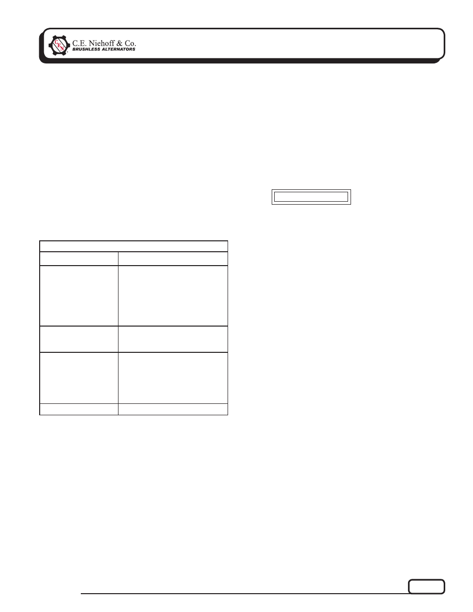
SYMPTOM
ACTION
TABLE 1 – System Conditions
Check: loose drive belt; low bat-
tery state of charge.
Check: current load on system
is greater than alternator
can produce.
Check: defective alternator
and/or regulator.
Check: wrong regulator.
Check: defective regulator.
Check: alternator.
Check: presence of energize
signal.
Check: battery voltage at alter-
nator output terminal.
Check: defective alternator
and/or regulator.
Go to Chart 2, page 5.
Low Voltage Output
High Voltage Output
No 28 V Output
C. Preliminary Check-out
Check symptoms in Table 1 and correct if necessary.
A. Tools and Equipment for Job
• Digital Multimeter (DMM)
• Ammeter (digital, inductive)
• Jumper wires
B. Identifi cation Record
List the following for proper troubleshooting:
Alternator
model
number
______________________
Regulator model number _____________________
Setpoint listed on regulator ____________________
T
T
T
Section 2: Basic Troubleshooting
No 14 V Output
CAUTION