C.E. Niehoff & Co. N1233 Troubleshooting Guides User Manual
Page 2
Page 2
TG0021A
Section 1: Wiring Diagrams
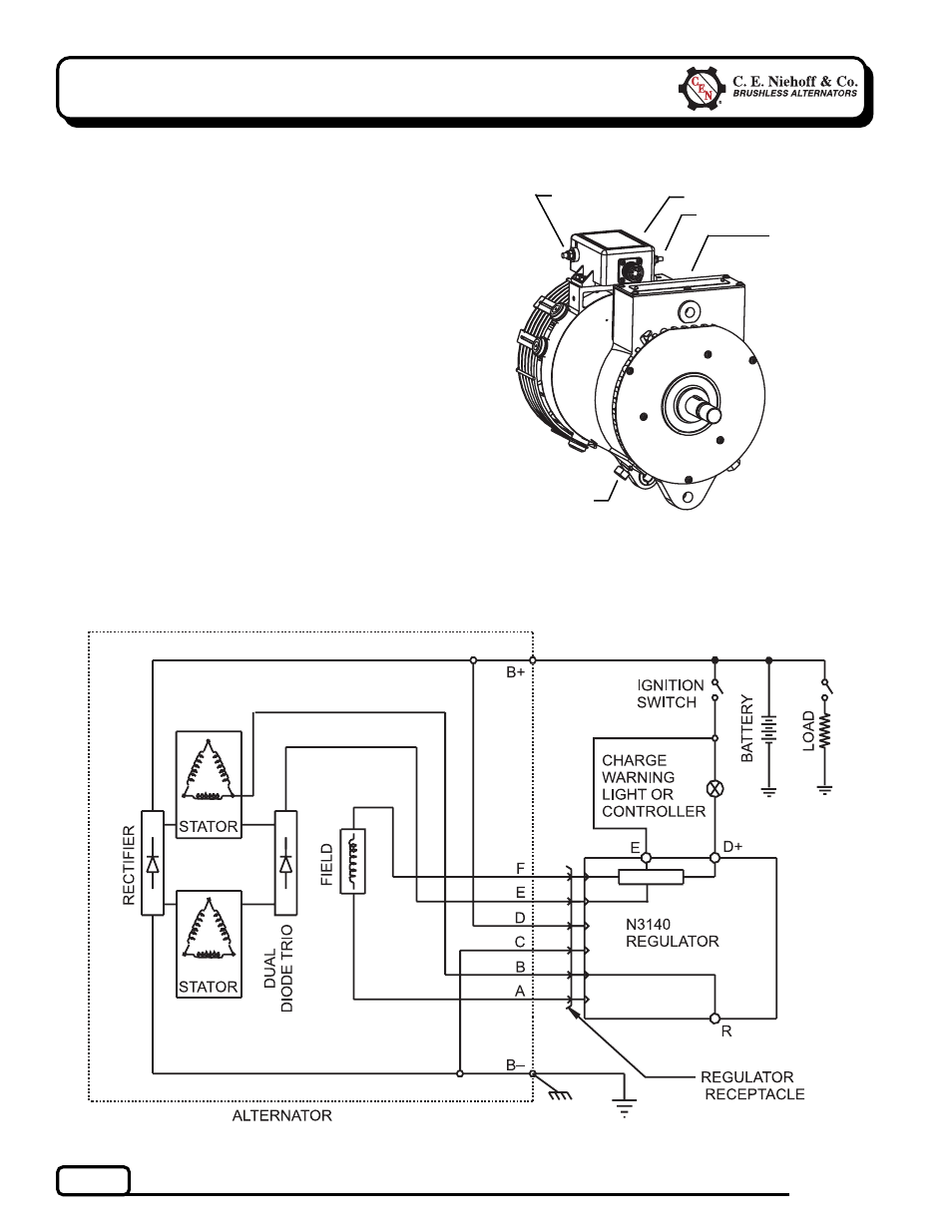
Figure 2 — N1233-2 Alternator with N3140 Regulator
Figure 1 — N1233-2 Alternator Terminals
(N3140 Regulator Attached to Alternator)
B– terminal
stud
D+ terminal
E terminal
B+ terminal stud
(on rear of
control unit)
! ! ! ! !
! ! ! ! !
R terminal
!
!
!
!
!
!
!
!
!
!
CEN N1233-2 Alternator
Description and Operation
N1233-2 28 V (260 A) alternator is self-rectifying.
All windings and current-transmitting components
are non-moving, so there are no brushes or slip rings
to wear out.
When controlled by the
N3140 regulator, this alter-
nator becomes externally energized through the E
terminal, connected to a switched power source to
turn on regulator. See wiring diagram. N3140 regula-
tor has:
• D+ terminal to provide signal to vehicle electrical
system, confirming alternator operation.
• R terminal to provide an optional AC voltage tap.
• overvoltage cutout (OVCO). Regulators with OVCO
(overvoltage cutout) will trip at vehicle electrical
system voltages
above 33 volts that exist longer
than 3 seconds. OVCO feature detects high
voltage and reacts by signaling relay in F+
alternator circuit to open. This turns off alterna-
tor. Restarting engine resets OVCO circuit.
Regulator regains control of alternator output
voltage.
!
!
!
!
!