Can/j1939 interface – C.E. Niehoff & Co. EPM Troubleshooting Guides User Manual
Page 3
Page 3
TG0051A
Section B: CAN/J1939 Diagnostics
CAN/J1939 Interface
DESCRIPTION AND OPERATION
The EPM is compatible with CAN bus standard for digital
networks and uses the SAE J1939 communications protocol.
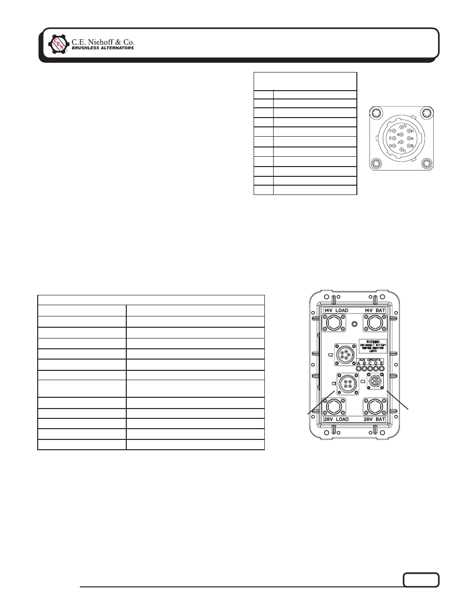
CEN uses MIL-STD connector MS3112E12-10P to interface
between the EPM and the DPA adapter used to monitor the
broadcast messages on the CAN bus line. The readouts of
these messages are shown in Table 2 for the EPM.
Pin
Identifi cation
TABLE 1 – J1939 Connector
Circuit Identifi cation
A
B
C
D
E
F
G
H
J
K
CAN High
CAN Low
CAN Shield
Ground
Restricted use
Restricted use
Restricted use
unused
unused
+28V power
Figure 3 – EPM Electric Power Manager
T
J1939
Connector
Under Cap
T
EPM
Connector
to
Regulator
EPM Readout
Expected Reading
TABLE 2 – EPM/J1939 Readout Diagnostics (With Engine Running)
Load Voltage 28 V System
Load Voltage 14 V System
Alternator Speed
Battery Voltage 28 V System
Battery Voltage 14 V System
EPM Temperature
Charging and Discharging
Current of 28 V Battery
Batt Charging 28 V LED
Batt Charging 14 V LED
Main Switches On
Cranking Detected
Emergency Flasher Detected
Figure 2 – J1939
Connector Pins
27–29 V
13.5–14.5 V
1200 to 6000 RPM
27–29 V
13.5–14.5 V
–50ºF (–46ºC) to 200ºF (93ºC)
10 A (varies according to battery condition)
OK
OK
OK
OK
OK