C.E. Niehoff & Co. C722 & C724 Troubleshooting Guides User Manual
Page 4
Page 4
TG71A
Section C: Advanced Troubleshooting
A2-214 Regulator on C724 Alternator
DESCRIPTION AND OPERATION
A2-214 regulator is attached directly to the outside of
alternator.
Main diagnostic feature of regulator is a green lens
LED located on the front of the regulator. LED indi-
cates whether regulator has been energized. See
Table 2 for LED indication and status.
Regulators with OVCO (overvoltage cutout) will trip at
vehicle electrical system voltages
above 32 volts that
exist longer than 3 seconds. OVCO feature detects
high voltage and reacts by signaling the F+ alternator
circuit to open. This turns off alternator. Restarting
engine resets OVCO circuit. Regulator regains control
of alternator output voltage.
TROUBLESHOOTING
Shut down vehicle and restart engine. If alternator
functions normally after restart, a “no output condi-
tion” was normal response of voltage regulator to
“high voltage” condition. Inspect condition of electri-
cal system, including loose battery cables, both posi-
tive and negative. If battery disconnects from system,
it could cause “high voltage” condition in electrical
system, causing OVCO circuit to trip.
If you have reset alternator once and electrical system
returns to normal charge voltage condition, there may
have been a one time, high voltage spike, causing
OVCO circuit to trip.
If OVCO circuit repeats cutout a second time in short
succession and shuts off alternator F+ circuit, try
third restart. If OVCO circuit repeats cutout, go to
Chart 1, page 5.
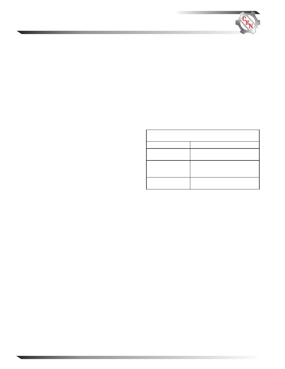
TABLE 2—A2-214 Regulator
LED Indications and Status
INDICATION
STATUS
ON steady
Normal regulator operation.
Alternator is producing output.
FLASHING
Regulator is receiving energize
signal. LED will flash until
alternator produces output.
OFF
Regulator is not receiving ener-
gize signal or OVCO has tripped.
A2-212 Regulator on C722 Alternator
DESCRIPTION AND OPERATION
A2-212 regulator is attached directly to the outside of
alternator.
Regulators with OVCO (overvoltage cutout) will trip at
vehicle electrical system voltages
above 32 volts that
exist longer than 3 seconds. OVCO feature detects
high voltage and reacts by signaling the F+ alternator
circuit to open. This turns off alternator. Restarting
engine resets OVCO circuit. Regulator regains control
of alternator output voltage.
TROUBLESHOOTING
Shut down vehicle and restart engine. If alternator
functions normally after restart, a “no output condi-
tion” was normal response of voltage regulator to
“high voltage” condition. Inspect condition of electri-
cal system, including loose battery cables, both posi-
tive and negative. If battery disconnects from system,
it could cause “high voltage” condition in electrical
system, causing OVCO circuit to trip.
If you have reset alternator once and electrical system
returns to normal charge voltage condition, there may
have been a one time, high voltage spike, causing
OVCO circuit to trip.
If OVCO circuit repeats cutout a second time in short
succession and shuts off alternator F+ circuit, try
third restart. If OVCO circuit repeats cutout, go to
Chart 1, page 5.