Page 4 tg31k – C.E. Niehoff & Co. C703/C703A & C706 Troubleshooting Guides User Manual
Page 4
Page 4
TG31K
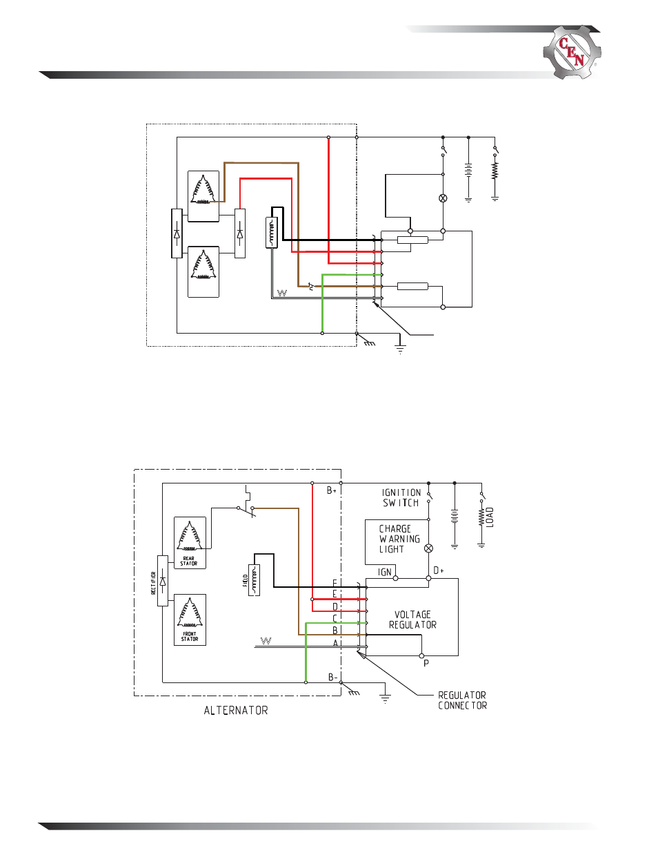
Section B: Schematic Diagram
Figure 6 — C703/C703A and C706 Schematic Diagrams
BR
BK
G
W
R
*
*Thermal switch is not factory-
installed on all models.
Schematic diagram for C703/C703A and C706 alternators without dual diode trio circuit.
Date code on or after Sept. 8, 2010 is stamped on DE housing.
Schematic diagram for C703/C703A and C706 alternators with dual diode trio circuit.
Date code before Sept. 8, 2010 is stamped on DE housing.
REGULATOR
RECEPTACLE
B+
Bñ
D+
R
E
RECTIFIER
DUAL
DIODE TRIO
FIELD
A2-212
REGULATOR
ALTERNATOR
LOAD
BA
TTER
Y
STATOR
STATOR
IGNITION
SWITCH
E
F
D
C
B
A
CHARGE
WARNING
LIGHT OR
CONTROLLER
THERMAL
SWITCH
W
BR
R
BK
G
R
*
*Thermal switch is not factory-
installed on all models.
IGN
P
B–
See also other documents in the category C.E. Niehoff & Co. Hardware:
- 5-Pin Connector Extended Wiring Harness Installation (1 page)
- 6-Pin Connector Extended Wiring Harness Installation (1 page)
- 6-Pin Connector Extended Wiring Harness W_O Fuses Installation (1 page)
- 100: Regulator Upgrade (1 page)
- 200 & 300: Regulator Upgrade Installation (2 pages)
- 600/700/800 Service Tool (1 page)
- A1-102/A1-104 Installation (2 pages)
- A2-149/A2-155 Regulator Installation (1 page)
- A2-213/A2-214 Regulator Installation (1 page)
- A2-317 Regulator Installation (1 page)
- A2-325/A2-330/A2-336 Regulator Installation (1 page)
- A2-334/A2-335 Regulator Installation (1 page)
- A2-337 Regulator Installation (1 page)
- A2-341/A2-346 Regulator Installation (1 page)
- A2-344/A2-348/A2-350 Regulator Installation (1 page)
- A2-349 Regulator Installation (1 page)
- A3-201 Adjustable Pulley Installation (2 pages)
- A6-141 & A6-143 Fan Guard Screw Replacement (1 page)
- A7-113/114/115 Stator & Shell Assy Replacement (1 page)
- A8-128 Power Management System Installation (1 page)
- A8-219 Low Frequency EMC Filter Assembly Installation (1 page)
- A9-305 Med-to-High Frequency EMC Filter Assembly Installation (2 pages)
- A9-307 Alternator Voltage Filter Instructions (1 page)
- A9-309 Inline Harness Instructions (1 page)
- A9-462 Energize Interrupt Switch Installation (1 page)
- A9-4011 Temperature Sense Lead Instructions (1 page)
- A9-4036 TV/J1939 Harness Installation (1 page)
- A9-4039/A9-4050 Temperature-Voltage Sense Harness Instructions (1 page)
- A9-4056 Temperature Sensor Replacement (1 page)
- C102/C102-1 Installation (2 pages)
- C130/C131/C132 Inst/Parts Rep/TG Combo Guide (12 pages)
- C130 & C132 Alternator Installation (4 pages)
- C131 Alternator Installation (4 pages)
- C180etc and C181etc Installation (4 pages)
- C190 Series Installation (4 pages)
- C321 Alternator Installation (1 page)
- C326 Installation (1 page)
- C510 Alternator Installation (2 pages)
- C520 Alternator/A2-326 Regulator w/Extended Wiring Harnesses Installation (1 page)
- C524, C524-1, -3, -4 Alternator/A2-334 & A2-335 Regulator Installation (1 page)
- C527 Alternator Installation (1 page)
- C540 Alternator Installation (2 pages)
- C600 & C700: Stator Change Instructions (1 page)
- C600: A4-106 Tension Link Adjuster Instructions (2 pages)
- C612: A9-169 Upgrade Bearing Kit Instructions (1 page)