C.E. Niehoff & Co. C672 Troubleshooting Guides User Manual
Page 2
Page 2
TG73A
Section A: Description/Operation
CEN C672 Alternator/Regulator Description
and Operation
C672 28 V (260 A) alternator is internally rectified. All
windings and current-transmitting components are
non-moving, so there are no brushes or slip rings to
wear out.
This alternator is externally energized when the battery
master switch on the vehicle is turned on and provides
power to the regulator through the ENG circuit (the
regulator can also operate without vehicle connection
to ENG, and instead provide power by sensing rotation
through the regulator’s AC circuit).
Field coil is then energized. AC is rectified into DC
output through diodes in anti-drive end rectifier hous-
ing and supplied to the battery from the alternator B+
circuit. See schematic diagram on page 3.
Alternator output current is self-limiting and will not
exceed rated capacity of alternator. Regulator maintains
alternator output voltage at pre-determined regulated
setting (see below for setpoints) as vehicle electrical
loads are switched on and off.
A2-342 regulator furnished with some units includes:
• No external terminals, only a special 3-pin vehicle
harness connector providing one pin for optional AC
voltage tap (PHASE OUT), one pin for DC voltage
signal to vehicle electrical system confirming alterna-
tor operation (D+), and one pin for the energize
connection (ENG). This regulator can function with
or without vehicle ignition. When necessary, ENG
circuit in vehicle 3-pin harness is connected to vehicle
ignition to provide battery voltage when engine is
running. Circuit should be off (no voltage present)
when vehicle ignition is off or engine is not running.
• Overvoltage cutout (OVCO). See page 4.
• Tricolored LED. See page 4.
• Battery type selection and battery maintenance/
function are the sole responsibilities of the customer.
• Temperature/voltage sense/J1939 connector to be
used with optional harness.
— When temperature/voltage sense/J1939 harness is
not connected, regulator will operate in fixed volt-
age setting determined by the select switch position
on the bottom of the regulator. See Column 2 in
Table
1.
— When temperature/voltage sense/J1939 harness is
connected, regulator will automatically optimize
the charge voltage for battery type based on tem-
perature. Also, vehicle manufacturer-requested
functions of J1939 interface are available through
connector. See Column 3 in Table 1.
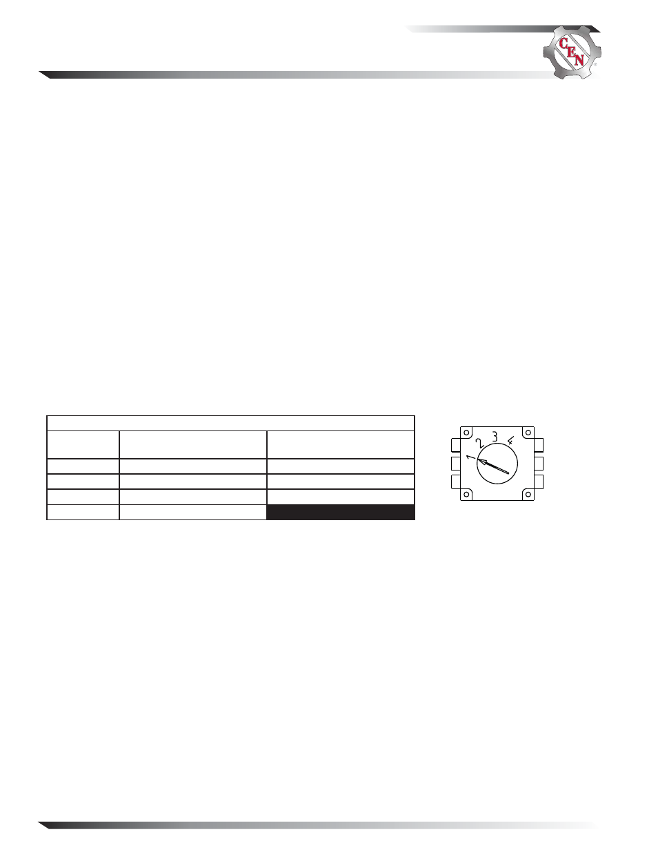
Figure 2 —Voltage/Battery Switch
Table 1 — A2-342 Regulator Voltage/Battery Switch Position
Switch Position
T/VS/J1939 Harness
Not Connected (Voltage Select)
T/VS/J1939 Harness
Connected (Battery Select)
Position 1
27.5 V
Maintenance (D Category)
Position 2
28.0 V
Maintenance-free (Group 31)
Position 3
28.5 V
AGM
Position 4
29.0 V
DO NOT USE POSITION # 4