Page 4 tg79a – C.E. Niehoff & Co. C659 Troubleshooting Guides User Manual
Page 4
Page 4
TG79A
Section C: On-Vehicle Troubleshooting
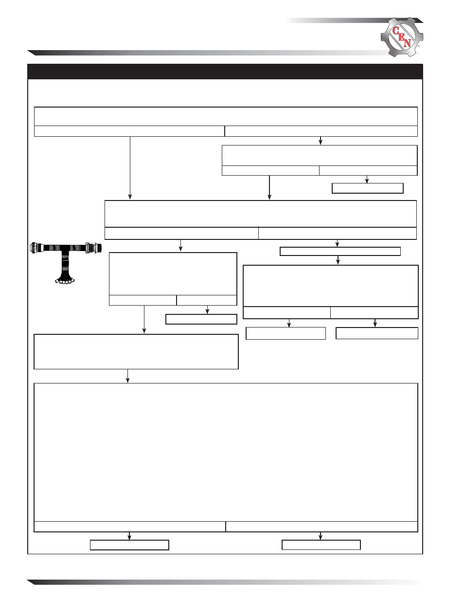
No Alternator Output – Test Charging Circuit
If you have questions about your alternator or any of these test procedures, or if you need to locate a Factory Authorized Service Dealer, please contact us at:
C.E. Niehoff & Co.• 2021 Lee Street • Evanston, IL 60202 USA
TEL: 800.643.4633 USA and Canada • TEL: 847.866.6030 outside USA and Canada • FAX: 847.492.1242
E-mail us at [email protected]
Before starting diagnostic sequence, verify the following and repair/replace if not to spec:
—batteries for state-of-charge (24.5-25.5 V), condition, and secure connections
—master battery switch for function
MASTER BATTERY SWITCH ON, KEY ON, ENGINE ON: Test for battery voltage across B+ terminal on alternator
and isolated B− terminal on alternator. Does battery voltage exist?
Yes
No
Figure 5 –
CEN 6-pin A10-114
Inline Harness Tool
Socket Connections
SOCKET CONNECTIONS
Socket A F
–
Socket B Phase
Socket C B –
Socket D B+
Socket E D+
Socket F F+
MASTER BATTERY SWITCH ON, KEY OFF, ENGINE OFF: Readings of all five tests must pass.
1. Battery voltage test: Connect DMM red lead to socket D in test tool. Connect DMM black lead to socket C in test tool.
Battery voltage should exist.
2. Field coil resistance test: Set DMM to ohms test. Field resistance between sockets F and A in test tool should
measure nominal 1.0-1.5 ± 0.2 ohms. Field coil is defective if reading is less than 0.5 ohms or greater than 3 ohms.
3. Significant magnetism test:
a. Securely connect one jumper wire between socket F in test tool and B+ terminal on alternator.
b. Insert one end of
second jumper wire in socket A in test tool. Momentarily (1 sec.) touch other end of second jumper
wire to alternator B– terminal. Spark will occur at B– terminal. Touch steel tool to shaft to detect significant magnetism.
c. Remove both jumper wires.
4. Turn off master battery switch. Disconnect B+ battery cable on alternator. Set DMM to diode test. Connect black
lead on DMM to socket E in test tool and red lead to B+ terminal on alternator. DMM should read OL. Reverse leads.
DMM should read OL again. Reconnect B+ battery cable to alternator. Turn on master battery switch.
5. Phase taps test: Set DMM to diode test. Connect DMM black lead to socket B in test tool. Connect red lead to alternator
B+ terminal. DMM should read blocking in this direction. Then reverse leads. DMM should read flow in this direction.
Repeat for socket B and B– terminal. Tests should read flow in one direction and blocking in the other direction.
Yes
No
Alternator is defective.
MASTER BATTERY SWITCH OFF, KEY OFF, ENGINE
OFF: Disconnect 6-pin alternator-to-regulator harness plug
at regulator and connect CEN A10-114 inline test tool to
harness plug end only. Make sure connections are secure.
Regulator is defective.
Repair vehicle wiring as necessary. Run engine and re-test
charging circuit. Is charging system performing properly?
System is operative.
No
Yes
A B C D E F
MASTER BATTERY SWITCH ON, KEY OFF, ENGINE OFF: Self-energized alternator may
have lost magnetism. Momentarily (1 sec.) jumper D+ terminal on regulator to B+ terminal on
alternator. Touch shaft with steel tool to detect significant magnetism. Is shaft magnetized?
Yes
No
Remove jumper from D+ to B+.
Install a jumper from B+ terminal on alternator to
pin F in harness plug. Momentarily (1 sec.) jumper
pin A to B– terminal on alternator. Touch shaft with
steel tool to detect significant magnetism. Is shaft
magnetized?
Yes
No
Alternator is defective.
Regulator is defective.
Residual magnetism has been
restored. Remove jumper from D+ to
B+. Run engine and re-test charging
circuit. Is charging system perform-
ing properly?
System is operative.
No
Yes