C.E. Niehoff & Co. C619/C630/N1222/N1223/A1-607/A1-608 Troubleshooting Guides User Manual
Page 6
Page 6
TG8B
Section C: Advanced Troubleshooting
(CONT’D)
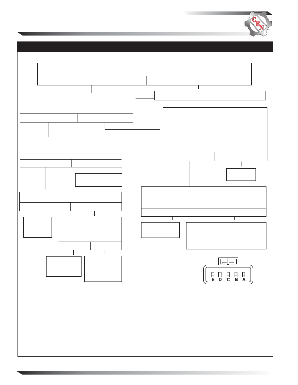
Chart 3 – No Alternator Output –
Ignition Switch – Test Charging Circuit
Jumper B+ terminal on alternator to E or IGN
terminal on alternator. Touch shaft with steel tool
to detect significant magnetism. Is shaft magnetized?
Yes
No
Disconnect jumper. Apply 12 V test light to
alternator E or IGN terminal and ground.
Does light glow brightly?
Yes
No
Run vehicle. Does charge voltage exist?
System
operating
normally.
Repair wiring or
ignition switch.
Yes
No
Jumper B+ terminal on
alternator to E or IGN termi-
nal on alternator. Does
charge voltage exist?
Yes
No
Repair wiring
or ignition
switch.
Contact CEN
Service
Department
for assistance.
Test for battery voltage at B+ terminal on alternator to ground, then at F+ terminal on alternator to
ground. Does battery voltage exist?
Yes
No
Repair vehicle wiring as necessary. Continue test.
STATIC TEST – ENGINE OFF, BATTERY SWITCH ON, KEY ON
Figure 4 – Alternator-to-Regulator Harness Plug
SOCKET CONNECTIONS
Socket A B–
Socket B Energize
Socket C Field –
Socket D Not Used
Socket E B+
Unplug alternator-to-regulator harness. Plug
CEN Regulator Bypass Adapter A10-129 into
harness plug and touch black lead to ground on
alternator case. (If no Adapter is available, con-
nect jumper wire from socket C on the harness
to ground). Spark will occur at ground. Touch
steel tool to shaft to detect significant magne-
tism. Is shaft magnetized?
Disconnect Regulator Bypass Adapter or jumper wire.
Connect DMM red lead to socket E in alternator-to-regula-
tor plug. Connect black lead to socket A in same plug.
Does battery voltage exist?
Regulator is
defective.
Yes
No
Check wiring and connections to
alternator.
Run engine and re-test charging
circuit for operation.
Yes
No
Alternator
is defective.