Br r bk g w – C.E. Niehoff & Co. C612/C617/C621/C624 Troubleshooting Guides User Manual
Page 3
Page 3
TG2D
Section A: Wiring Diagrams
(CONT’D)
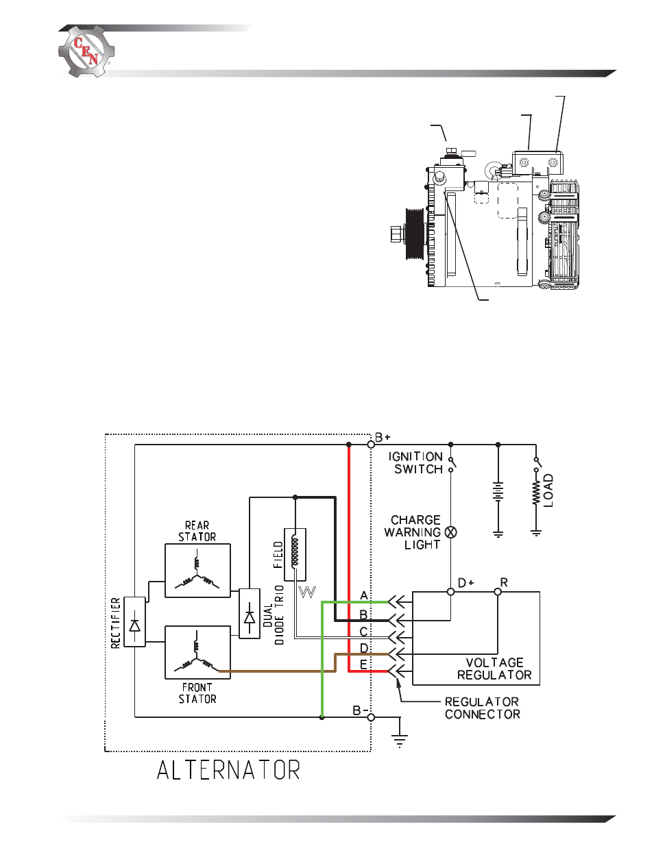
CEN C621 Alternator
Description and Operation
C621 28 V (220 A) alternators are self-rectifying and
self-energized. All windings and current-transmitting
components are non-moving, so there are no brushes or
slip rings to wear out.
When controlled by the
A2-141 regulator, these alterna-
tors become self-energizing through internal diode
trios. Residual magnetic field induces small voltage in
stator and energizes field coil. Field coil continues
receiving incremental voltage until full voltage is
achieved. AC is rectified into DC output through diodes.
Regulator controls voltage output. Regulator has:
• D+ terminal to provide a signal to vehicle electrical
system, confirming alternator operation
• P terminal to provide an optional AC voltage tap.
Figure 4 — C621 Alternator Terminals
Figure 5 — C621 Alternator Wiring Diagram
B– Ground Bolt
B+ Terminal
D+ Terminal
R or P Terminal
BR
R
BK
G
W
- 5-Pin Connector Extended Wiring Harness Installation (1 page)
- 6-Pin Connector Extended Wiring Harness Installation (1 page)
- 6-Pin Connector Extended Wiring Harness W_O Fuses Installation (1 page)
- 100: Regulator Upgrade (1 page)
- 200 & 300: Regulator Upgrade Installation (2 pages)
- 600/700/800 Service Tool (1 page)
- A1-102/A1-104 Installation (2 pages)
- A2-149/A2-155 Regulator Installation (1 page)
- A2-213/A2-214 Regulator Installation (1 page)
- A2-317 Regulator Installation (1 page)
- A2-325/A2-330/A2-336 Regulator Installation (1 page)
- A2-334/A2-335 Regulator Installation (1 page)
- A2-337 Regulator Installation (1 page)
- A2-341/A2-346 Regulator Installation (1 page)
- A2-344/A2-348/A2-350 Regulator Installation (1 page)
- A2-349 Regulator Installation (1 page)
- A3-201 Adjustable Pulley Installation (2 pages)
- A6-141 & A6-143 Fan Guard Screw Replacement (1 page)
- A7-113/114/115 Stator & Shell Assy Replacement (1 page)
- A8-128 Power Management System Installation (1 page)
- A8-219 Low Frequency EMC Filter Assembly Installation (1 page)
- A9-305 Med-to-High Frequency EMC Filter Assembly Installation (2 pages)
- A9-307 Alternator Voltage Filter Instructions (1 page)
- A9-309 Inline Harness Instructions (1 page)
- A9-462 Energize Interrupt Switch Installation (1 page)
- A9-4011 Temperature Sense Lead Instructions (1 page)
- A9-4036 TV/J1939 Harness Installation (1 page)
- A9-4039/A9-4050 Temperature-Voltage Sense Harness Instructions (1 page)
- A9-4056 Temperature Sensor Replacement (1 page)
- C102/C102-1 Installation (2 pages)
- C130/C131/C132 Inst/Parts Rep/TG Combo Guide (12 pages)
- C130 & C132 Alternator Installation (4 pages)
- C131 Alternator Installation (4 pages)
- C180etc and C181etc Installation (4 pages)
- C190 Series Installation (4 pages)
- C321 Alternator Installation (1 page)
- C326 Installation (1 page)
- C510 Alternator Installation (2 pages)
- C520 Alternator/A2-326 Regulator w/Extended Wiring Harnesses Installation (1 page)
- C524, C524-1, -3, -4 Alternator/A2-334 & A2-335 Regulator Installation (1 page)
- C527 Alternator Installation (1 page)
- C540 Alternator Installation (2 pages)
- C600 & C700: Stator Change Instructions (1 page)
- C600: A4-106 Tension Link Adjuster Instructions (2 pages)
- C612: A9-169 Upgrade Bearing Kit Instructions (1 page)