C.E. Niehoff & Co. N3237 Regulator Installation User Manual
N3237 regulator, Installation instructions
II0123A
Page 1 of 1
N3237
Regulator
C. E. Niehoff & Co. • 2021 Lee Street • Evanston, IL 60202 Tech Services Hotline 800-643-4633
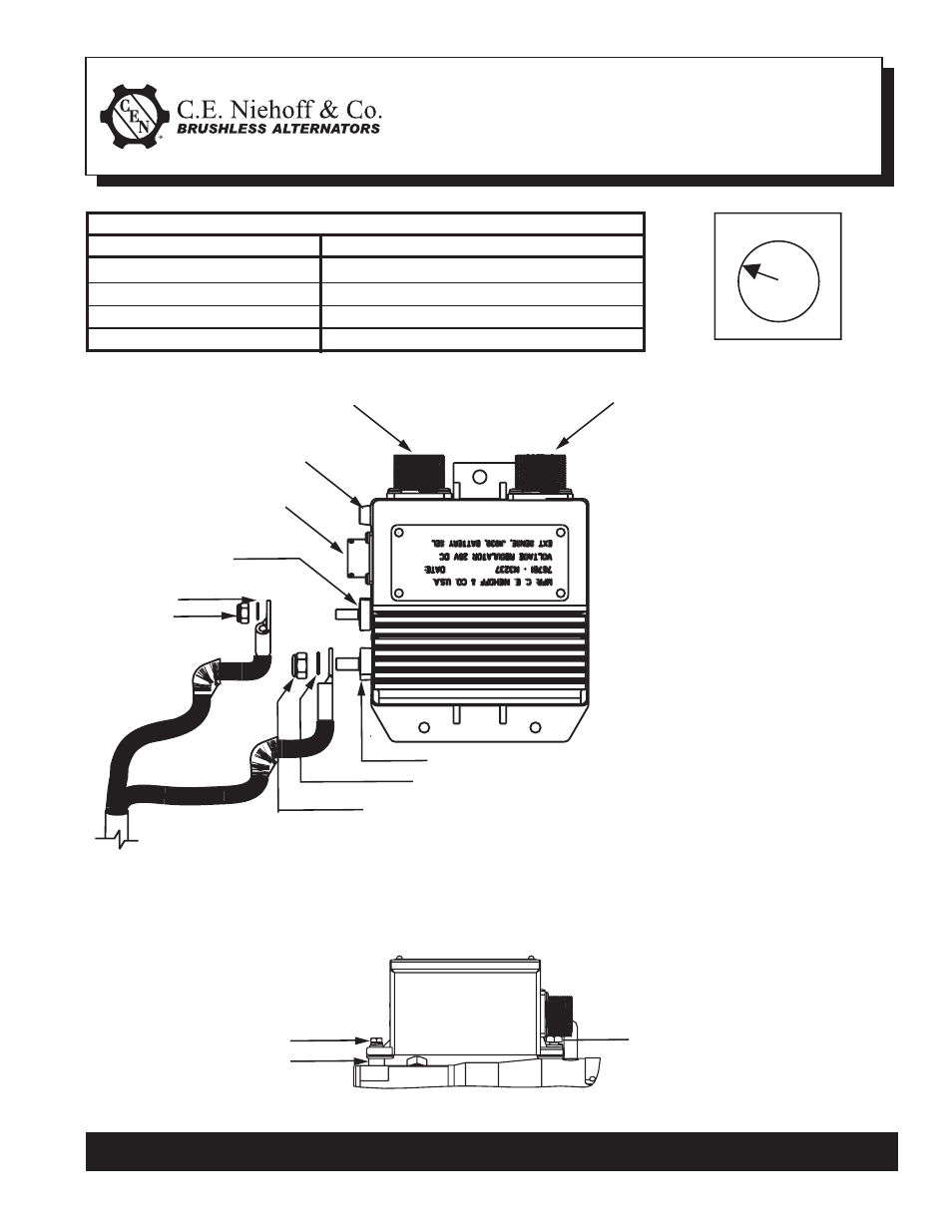
Table 1 – Voltage Select Switch Position
4 Voltage Setpoints (Fig. 1)
Position 1
Position 2
Position 3
Position 4
Customer Battery Requirements
Hawker Only (Factory Setting)
6TMF Only
Hawker & 6TMF
Other Type Battery
Figure 1 – Battery Selection
1. Before installing, turn regulator
over and select appropriate
battery type (See Table 1 and
Fig. 1).
2. Install regulator as described
in Figure 2.
3. Plug both alternator-to-regula-
tor harnesses into the regulator.
4. If vehicle interface receptacle is
unused it must be sealed with
MS3181-12 connector cover or
equivalent.
5. LED:
• flash RED when voltage is 2V
above
setpoint
• flash AMBER when voltage is
2V below setpoint or shaft not
rotating
• flash GREEN when voltage
within 2V of setpoint
• steady RED when regulator
shuts down due to sustained
high
voltage
Installation Instructions
1
2 3
4
Figure 2 – N3237 Regulator
Vehicle interface receptacle
Regulator-to-alternator harness receptacle
(not functional in this model)
Regulator-to-alternator harness receptacle
LED
AC terminal
Washer
M5 Locknut – torque to 3.4 Nm/30 lb.in.
IGN terminal
Washer
M6 Locknut –
torque to
3.4 Nm/30 lb.in.
#10-32 UNF-2A Screw,
Lockwasher,
Washer —
torque to 3.4Nm/30 lb. in.
Spacer
2 Places:
1/4-28 UNF-2A Screw—
torque to 8.5Nm/75 lb. in.